Decision timing synchronous circuit and receiver circuit

a timing synchronization and receiver circuit technology, applied in the direction of synchronisation signal speed/phase control, multiplex communication, digital transmission, etc., can solve the problem of difficult to recognize the optimum decision timing simply with the correlation value, and reducing the circuit scale. , to achieve the effect of improving the resistance to offs

Inactive Publication Date: 2007-06-28
LAPIS SEMICON CO LTD
View PDF9 Cites 4 Cited by
  • Summary
  • Abstract
  • Description
  • Claims
  • Application Information

AI Technical Summary

Benefits of technology

[0015]According to the present invention, it is possible to recognize the optimum decision timing even in an environment with reduced noise, thereby allowing for providing improved resistance to offsets while reducing the circuit scale.

Problems solved by technology

However, the aforementioned decision timing recognition method that employs the conventional baseband receiver circuit has the following problems.
Accordingly, this leads to a tremendous increase in the scale of the circuit for determining decision timing.
However, when a received signal is provided in an environment without so much noise, a plurality of maximal correlation values appearing successively may make it uncertain where the optimum timing is available, thus causing it difficult to recognize the optimum decision timing simply with the correlation value.

Method used


Image

  • Decision timing synchronous circuit and receiver circuit
  • Decision timing synchronous circuit and receiver circuit
  • Decision timing synchronous circuit and receiver circuit

Examples


first embodiment

(A) First Embodiment

[0030]Now, a detailed description will be made to a decision timing synchronous circuit and a receiver circuit according to a first embodiment of the present invention with reference to the drawings.

[0031]In accordance with the embodiment, the description will be made to a receiver circuit which generates a demodulated signal from a detected signal received using the decision timing provided by the decision timing synchronous circuit of the present invention.

[0032](A-1) Arrangement of the First Embodiment

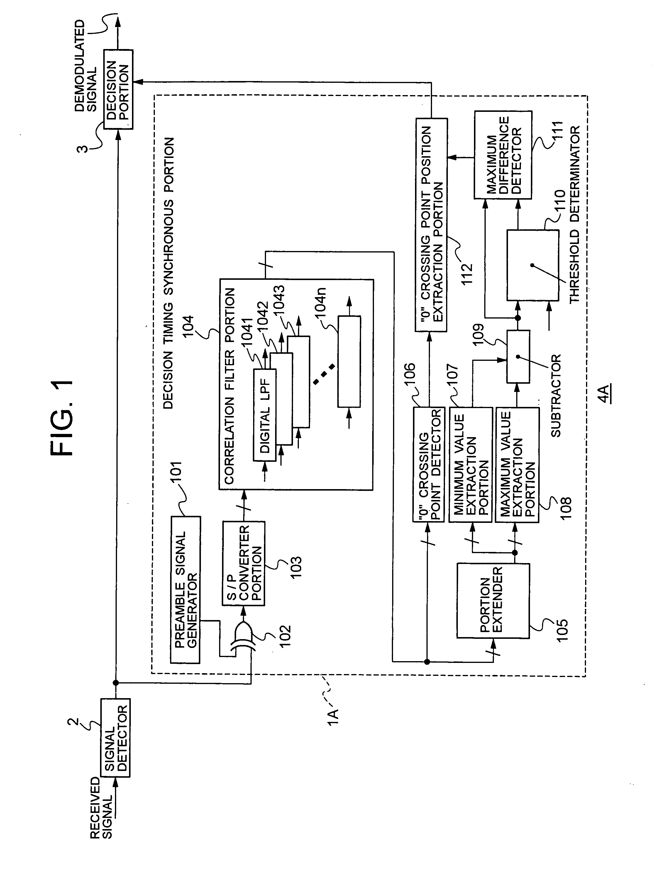
[0033]FIG. 1 is a block diagram illustrating the main internal configuration of the receiver circuit according to the embodiment. In FIG. 1, a receiver circuit 4A of the embodiment is configured to include a signal detector 2, a decision timing synchronous portion 1A, and a decision portion 3.

[0034]The signal detector 2 detects a received signal to provide a signal, which is binarized based on the detection result, to the decision timing synchronous portion 1A an...

second embodiment

(B) Second Embodiment

[0101]Now, a description will be made to a decision timing synchronous circuit and a receiver circuit according to a second embodiment of the present invention with reference to the drawings.

[0102]FIG. 8 is a block diagram illustrating the main internal configuration of a receiver circuit 4B according to the second embodiment.

[0103]The arrangement of the second embodiment is different from the arrangement of the first embodiment in that a decision timing synchronous portion 1B of the second embodiment includes an interpolator 113 for interpolating the values between the sampling timings output from the correlation filter portion 104.

[0104]Since the other components correspond to those of the first embodiment, FIG. 8 shows the components with the symbols corresponding to those of FIG. 1. Furthermore, the detailed description below relates to the interpolator 113 which is characteristic to the second embodiment, and thus the other components, which have already be...

third embodiment

(C) Third Embodiment

[0116]Now, a description will be made to a decision timing synchronous circuit and a receiver circuit according to a third embodiment of the present invention with reference to the drawings.

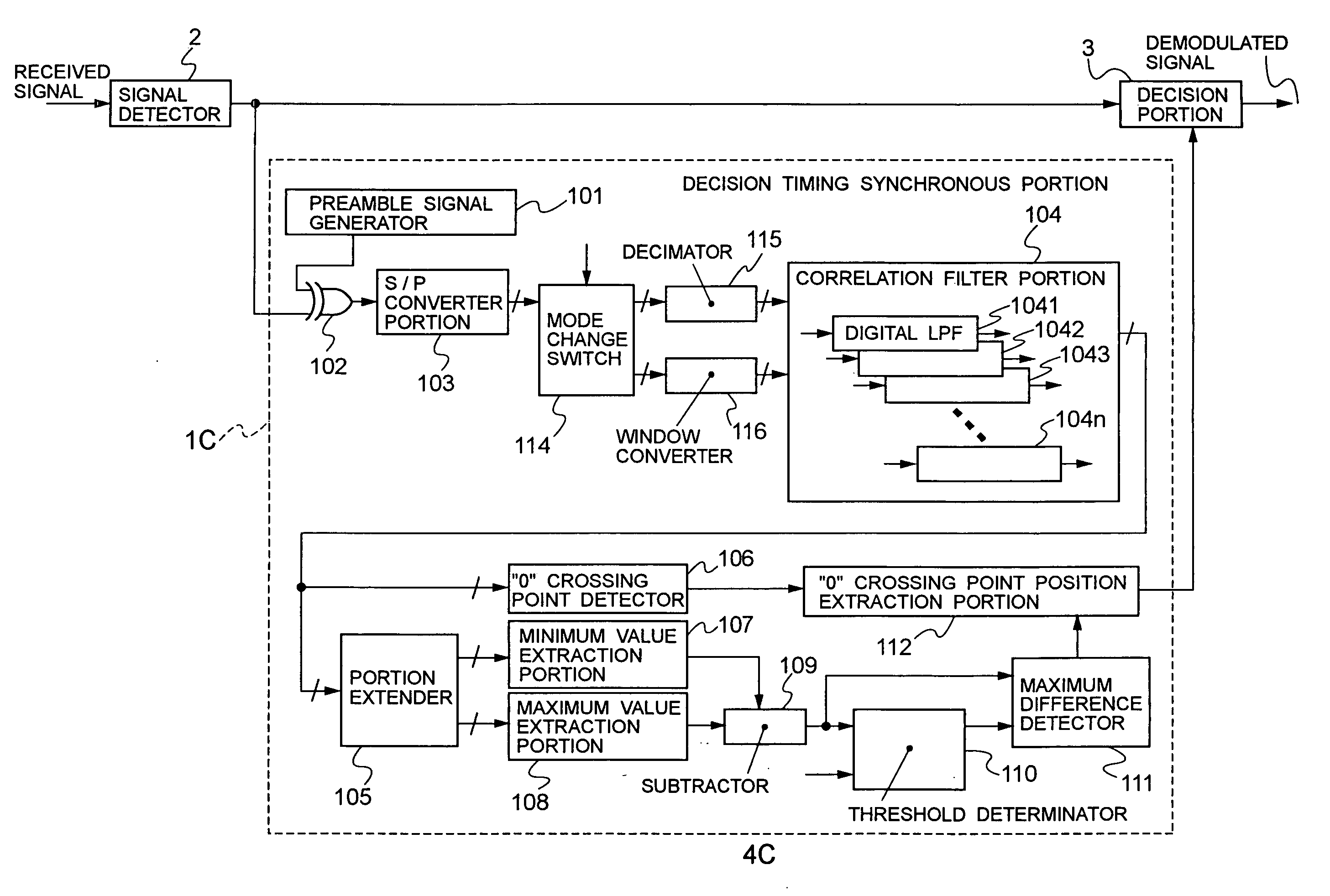
[0117]FIG. 10 is a block diagram illustrating the main internal configuration of a receiver circuit 4C according to the third embodiment.

[0118]The third embodiment is different from the first embodiment in that a decision timing synchronous portion 1C of the third embodiment includes a mode change switch 114, a decimator 115, and a window converter 116 between the S / P converter portion 103 and the correlation filter portion 104.

[0119]Since the other components correspond to those of the first embodiment, FIG. 10 shows the components with the symbols corresponding to those of FIG. 1. Furthermore, the description below relates to the arrangement that is characteristic to the third embodiment, and thus the other components, which have already been described in relation to the fir...


PUM


Abstract

A circuit includes: a portion for performing a logical operation based on a binary modulated signal and a cyclic signal; serial-to-parallel converter for sampling a operation output for parallel output; correlation filter having multiple digital filters for allowing the parallel signal values to pass therethrough; maximum difference detector for detecting a maximum difference in a period during which a difference between the maximum and minimum output signal values from digital filters is greater than a threshold; timing detector for detecting the inversion timing of each output signal value; and decision timing exterminating portion for determining decision timing based on the maximum difference and the detected inversion timing.

Description

BACKGROUND OF THE INVENTION[0001]1. Field of the Invention[0002]The present invention relates to decision a timing synchronous circuit and a receiver circuit, and more particularly, to a decision timing synchronous circuit and a receiver circuit which extract the optimum decision timing in generating a demodulated signal from a signal that is oversampled at a frequency higher than the modulation rate of a received signal.[0003]2. Description of the Related Art[0004]For example, Bluetooth (registered trademark) receivers in a Bluetooth system or a wireless communication system employ 2.4 GHz band radio signals. Such a Bluetooth receiver includes a RFIC (Radio Frequency Integrated Circuit) transceiver for extracting a baseband signal at a 1 MHz symbol transmission rate from the aforementioned 2.4 GHz band radio signals, and a baseband receiver circuit for assembling a packet from the extracted baseband signal (digital serial signal).[0005]Transmission of the baseband signal is initiat...

Claims


Application Information

Patent Timeline
Patent Type & Authority Applications(United States)
IPC IPC(8): H04L7/00
CPCH04L7/08
Inventor AKAHORI, HIROJI
Owner LAPIS SEMICON CO LTD
Why Eureka
Try Eureka