Liquid crystal display device

a display device and liquid crystal technology, applied in the direction of thin material processing, instruments, chemistry apparatus and processes, etc., can solve the problems of reducing the afterimage characteristics, thermal stability or electric stability, and the amount of fine decomposition product generation by ultraviolet ray cutting is not considered, and achieves high polarity and high-quality image display

Active Publication Date: 2007-06-28
PANASONIC LIQUID CRYSTAL DISPLAY CO LTD +1
View PDF1 Cites 10 Cited by
  • Summary
  • Abstract
  • Description
  • Claims
  • Application Information

AI Technical Summary

Benefits of technology

[0021] According to the invention, it is possible to suitably inhibit adsorption of an ion in the liquid crystal to the polar portion of a film molecule of the orientation film (for example, the terminal of polyimide, the imide ring C═O of polyimide, a case where there is a substituent with a high polarity as a side chain of polyimide). By this, the degradation of afterimage characteristics due to DC by the adsorption of an ion impurity is suppressed, and a high-quality image display can be obtained.

Problems solved by technology

However, in the related art, the generation amount of fine decomposition product by cutting of ultraviolet rays is not considered.
The decomposition product reduces afterimage characteristics, thermal stability or electric stability and has been a factor to degrade the display performance according to the amount thereof.

Method used


Image

  • Liquid crystal display device
  • Liquid crystal display device
  • Liquid crystal display device

Examples


examples 1

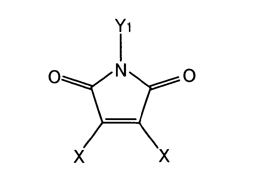
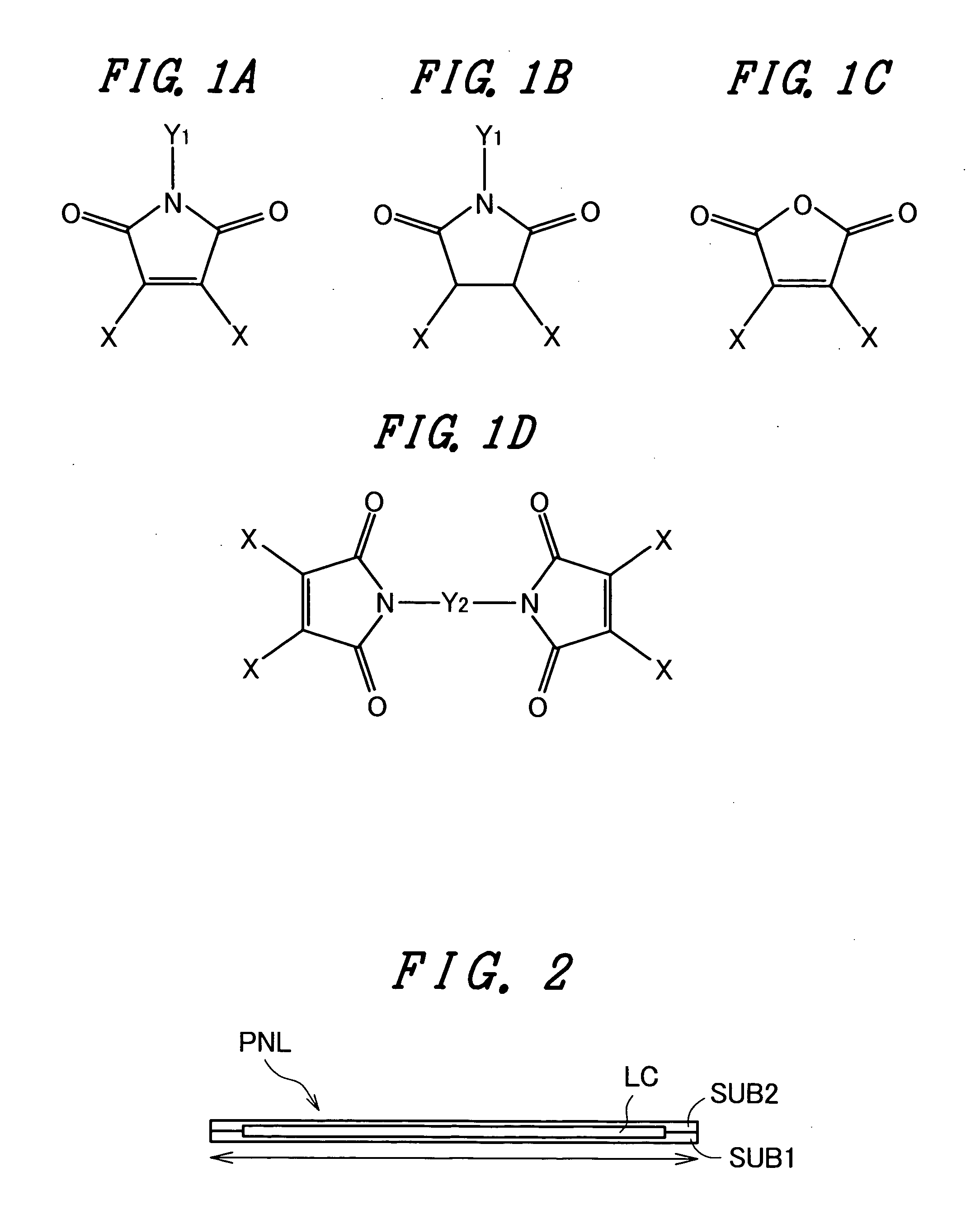
[0037]FIGS. 1A to 1D are explanatory views of typical structural formulae of short molecule components as decomposition products due to an orientation film resulting from a light orientation treatment in the invention. Here, although only the typical structures are shown, it is needless to say that the invention is not limited to these.

[0038] Incidentally, in FIG. 1, X denotes bonding of H, CH3, (CH2)n—CH3, (CF2)n—CF3 or the like. Besides, Y1 denotes bonding of H, CH3or one of materials shown in FIGS. 10A to 10E. Besides, Y2 denotes bonding of one of materials shown in FIGS. 11A to 11E.

[0039] In this example, verification will be made on the influence, given to the function of the orientation film, of the residual amount of the decomposition product. Specifically, liquid crystal display (LCD) panels having orientation films of various conditions are produced by materials indicated below.

[0040] Condensation polymer of BAPP / CBDA (Mw=50000) [0041] BAPP; 2, 2-bith{4-(para-aminophenox...


PUM

PropertyMeasurementUnit
thicknessaaaaaaaaaa
thicknessaaaaaaaaaa
side lengthaaaaaaaaaa

Abstract

In a liquid crystal display device using a photodecomposition type light orientation film, the deterioration of display performance due to an impurity resulting from a light orientation treatment of the orientation film is suppressed to enable high-quality image display. In the orientation film to which a liquid crystal orientation function is provided, the amount of decomposition product due to the orientation film is 3957.5 ng or less per 100 cm2.

Description

[0001] The present application claims priority from Japanese application JP2005-371409 filed on Dec. 26, 2005 and Japanese application JP2006-328070 filed on Dec. 5, 2006, the content of which is hereby incorporated by reference into this application. BACKGROUND OF THE INVENTION [0002] 1. Field of the Invention [0003] The present invention relates to a liquid crystal display device, and particularly to a liquid crystal display device in which an orientation control function is provided to an orientation film by light irradiation. [0004] 2. Description of the Related Art [0005] As a method of performing an orientation treatment, that is, providing an orientation control function to an orientation film used in a liquid crystal display device, there has been a method of performing a rubbing treatment. In the orientation treatment by rubbing, the orientation film is rubbed by a cloth in a specified direction so that the orientation treatment is performed. On the other hand, as a method ...

Claims


Application Information

Patent Timeline
Patent Type & Authority Applications(United States)
IPC IPC(8): C09K19/00
CPCC09K19/54Y10T428/1005G02F1/133788G02F1/133711C09K2323/02
Inventor SAKAI, AKIKUNIMATSU, NOBORUSONODA, HIDEHIROMATSUYAMA, SHIGERU
Owner PANASONIC LIQUID CRYSTAL DISPLAY CO LTD
Why Eureka
Try Eureka