Single, multi-walled, functionalized and doped carbon nanotubes and composites thereof

a technology of carbon nanotubes and carbon nanotubes, which is applied in the field of single walled and multi-walled carbon nanotubes (cnts), functionalized carbon nanotubes and carbon nanotube composites, and can solve problems such as non-uniform cnts

Active Publication Date: 2007-06-28
CANATU OY
View PDF12 Cites 68 Cited by
  • Summary
  • Abstract
  • Description
  • Claims
  • Application Information

AI Technical Summary

Benefits of technology

[0017] (j) deposition of gas dispersions of produced CNTs and / or composite CNT formulations onto surfaces and / or into matrix and / or layered structures and / or devices when desired.
[0018] The present invention includes one or more CNT reactors, which can allow continuous or batch production of CNTs, functionalized CNTs, doped CNTs and composites thereof. The present invention allows all or part of the processes of synthesis of CNTs, their purification, doping, functionalization, coating, mixing and deposition to be combined in one continuous procedure and in which the catalyst synthesis, the CNT synthesis, and their functionalization, doping, coating, mixing and deposition can be separately controlled. The present invention further provides a composition of matter comprising single walled and multi-walled CNTs and structures and devices fabricated from the same.

Problems solved by technology
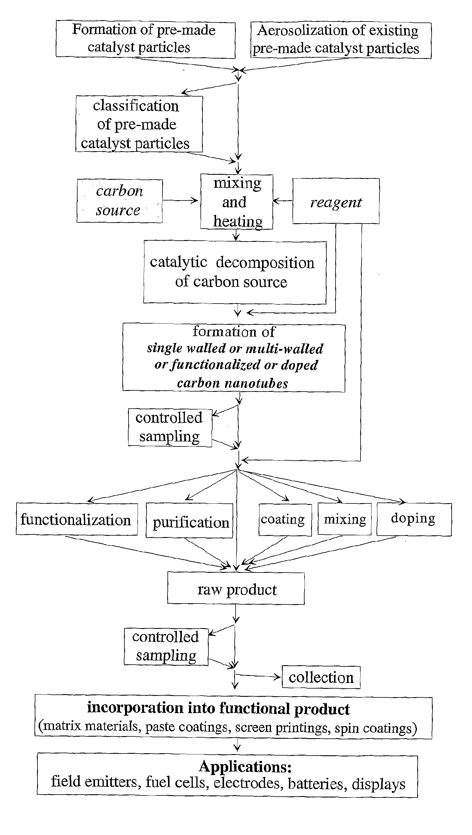
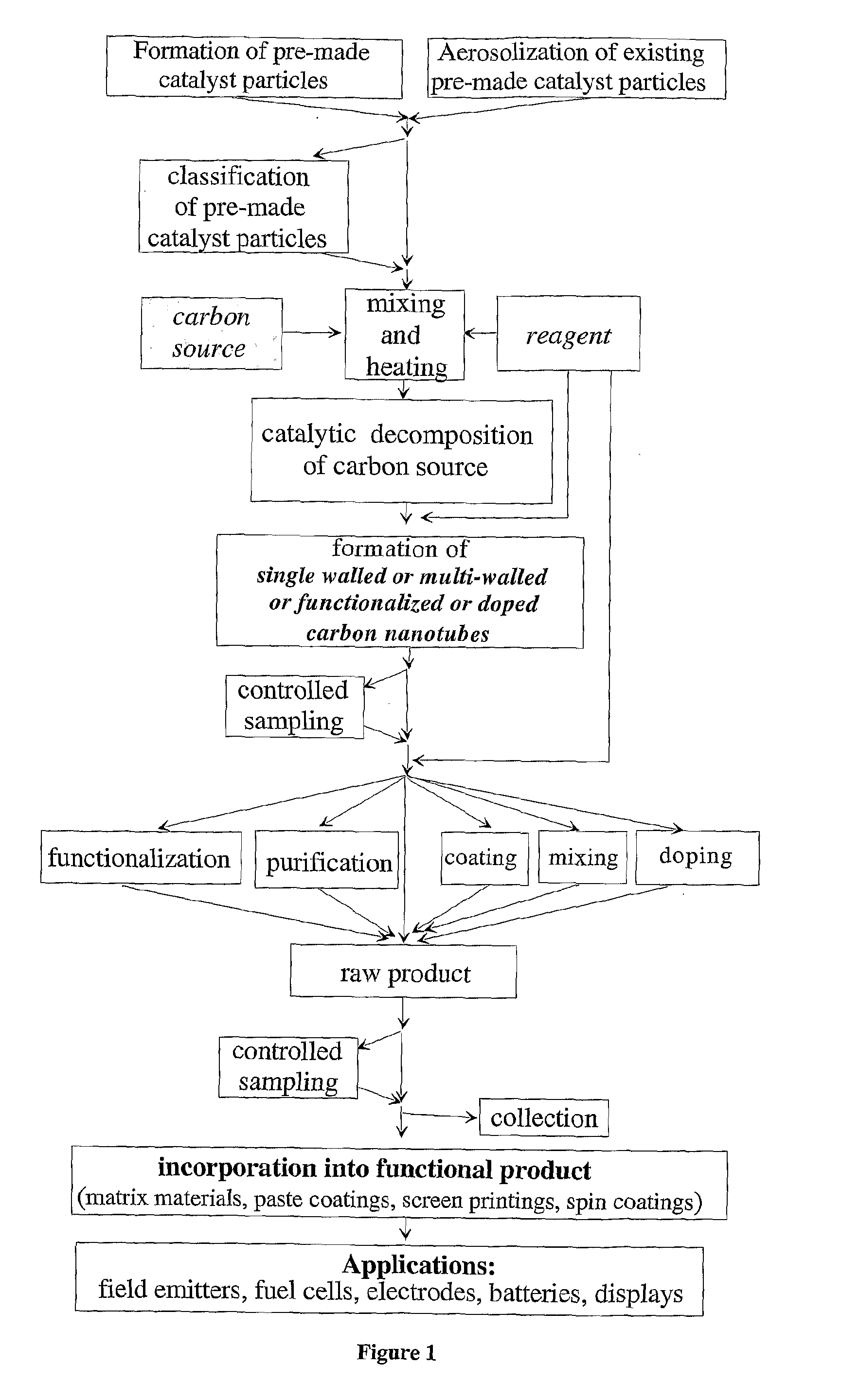
Though patent US 2002 / 102193 A describes a means of separately producing catalyst particles and CNTs, it does not specify a means of controlling the high non-uniformity of catalyst particles produced by the chemical nucleation method proposed and thus will tend to produce non-uniform CNTs.

Method used


Image

  • Single, multi-walled, functionalized and doped carbon nanotubes and composites thereof
  • Single, multi-walled, functionalized and doped carbon nanotubes and composites thereof
  • Single, multi-walled, functionalized and doped carbon nanotubes and composites thereof

Examples


example 1

Single Walled CNT Synthesis from Carbon Monoxide as Carbon Source Using Iron as Catalyst Material and Using a Ceramic Reactor Tube

[0148] Carbon source: CO.

[0149] Catalyst particle source: hot wire generator.

[0150] Catalyst material: iron wire of 0.25 mm in diameter.

[0151] Operating furnace temperature: 1200° C.

[0152] Operating flow rates: CO outer flow of 400 cm3 / min and hydrogen / nitrogen (7 / 93) inner flow of 400 cm3 / min.

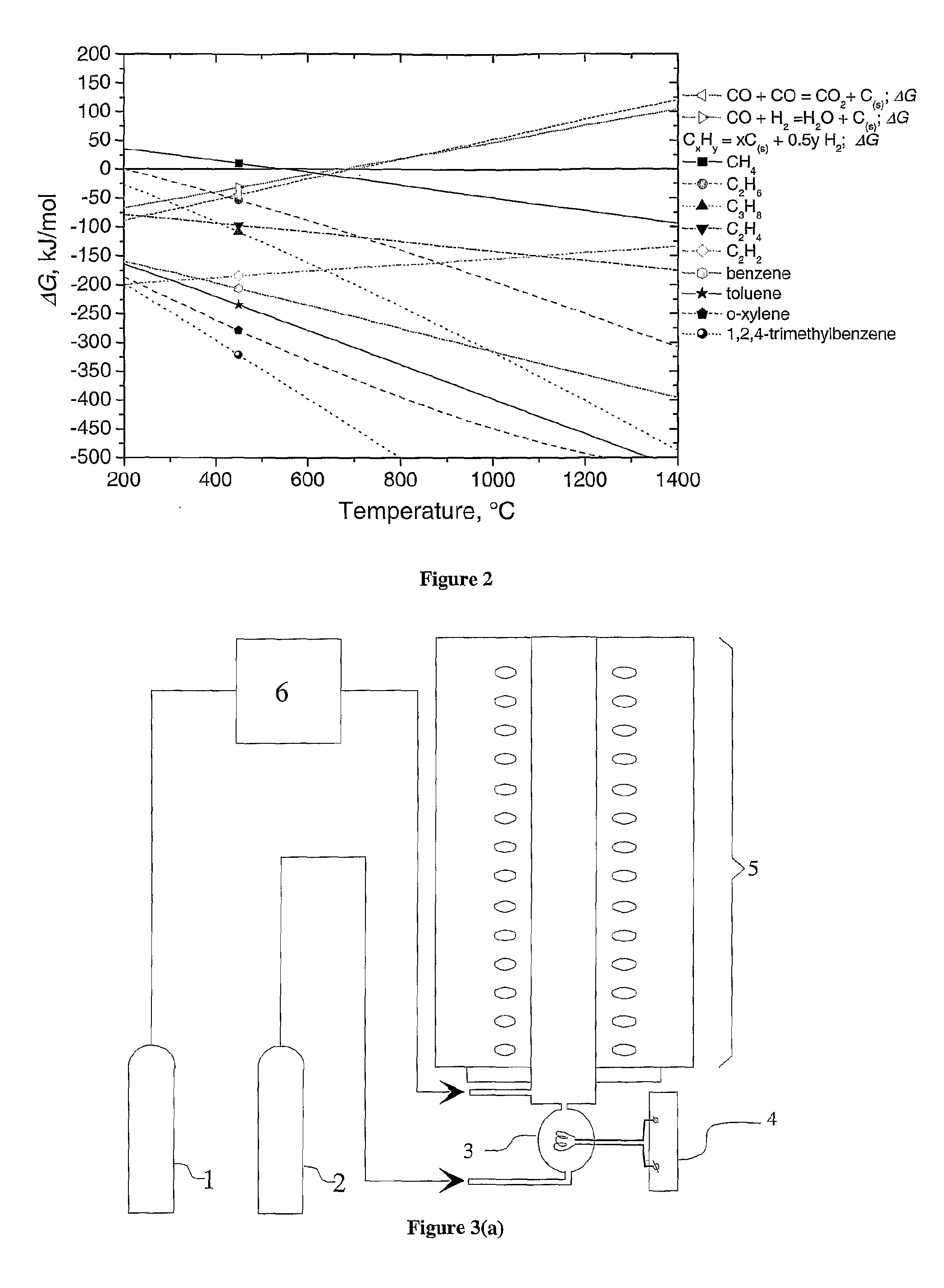
[0153] This example, illustrating the synthesis of single walled CNTs, was carried out in the embodiment of the invention shown in FIG. 3(b). Carbon monoxide was supplied from a gas cylinder (1) and the experimental setup did not contain a saturator (6). The embodiment consisted of a HWG smoothly integrated with a heated vertical tubular CNT reactor. A ceramic tube, with an internal diameter of 22 mm inserted inside the 90-cm length furnace (Entech, Sweden) was used as a CNT reactor. Inside the CNT reactor another ceramic tube with external and internal diamet...

example 2

Number Distributions of Length and Diameters of Single Walled CNTs Produced at Various Conditions and Using a Ceramic Reactor Tube

[0159] Carbon source: CO.

[0160] Catalyst particle source: hot wire generator.

[0161] Catalyst material: iron wire of 0.25 mm in diameter.

[0162] Operating furnace temperature: 1000, 1200, 1400° C.

[0163] Operating flow rates: hydrogen / nitrogen (7 / 93) inner flow of 400 cm3 / min; [0164] CO outer flow: 400, 590, 765 cm3 / min.

[0165] The example of the CNTs produced at 1200° C. and at equal internal H2 / N2 and external CO flow rates of 400 cm3 / min is described and shown in Example 1.

[0166] Number diameter and length distributions of the produced CNTs were obtained on the basis of high-resolution TEM images and presented in FIG. 10(a) and FIG. 10(b). The investigations of the influence of the experimental conditions on the CNT dimensions were carried out at a fixed hydrogen / nitrogen inner flow of 400 cm3 / min varying the furnace temperature from 1000 to 1200 to...

example 3

Single Walled CNT Synthesis from Carbon Monoxide as Carbon Source Using Iron as Catalyst Material and Using a Stainless Steel Reactor Tube

[0170] Reactor tube: stainless steel with a composition of Fe 53, Ni 20, Cr 25, Mn 1.6, Si, C 0.05 weight %.

[0171] Carbon source: CO.

[0172] Catalyst particle source: hot wire generator.

[0173] Catalyst material: iron wire of 0.25 mm in diameter.

[0174] Set furnace temperature: 900° C., corresponding to maximum furnace temperature of around tmax=1070° C.

[0175] Operating flow rates: CO outer flow of 400 cm3 / min and hydrogen / nitrogen (7 / 93) inner flow of 400 cm3 / min.

[0176] This example, illustrating the synthesis of single walled CNTs, was carried out in the embodiment of the invention shown in FIG. 3(b), wherein the reactor tube was made of stainless steel so as to provide saturated wall conditions for the iron vapor. FIG. 11 demonstrates the product formed at the given operating conditions. The product consists of bundles of single walled CNTs...


PUM

PropertyMeasurementUnit
temperaturesaaaaaaaaaa
temperatureaaaaaaaaaa
particle sizeaaaaaaaaaa

Abstract

The present invention relates to single walled and multi-walled carbon nanotubes (CNTs), functionalized CNTs and carbon nanotube composites with controlled properties, to a method for aerosol synthesis of single walled and multi-walled carbon nanotubes, functionalized CNTs and carbon nanotube composites with controlled properties from pre-made catalyst particles and a carbon source in the presence of reagents and additives, to functional, matrix and composite materials composed thereof and structures and devices fabricated from the same in continuous or batch CNT reactors. The present invention allows all or part of the processes of synthesis of CNTs, their purification, doping, functionalization, coating, mixing and deposition to be combined in one continuous procedure and in which the catalyst synthesis, the CNT synthesis, and their functionalization, doping, coating, mixing and deposition can be separately controlled.

Description

1. BACKGROUND OF THE INVENTION [0001] 1. Field of the Invention [0002] The present invention relates to single walled and multi-walled carbon nanotubes (CNTs), functionalized carbon nanotubes and carbon nanotube composites with controlled properties, to a method for aerosol synthesis of single walled and multi-walled carbon nanotubes, functionalized carbon nanotubes and carbon nanotube composites with controlled properties from pre-made catalyst particles and a carbon source in the presence of reagents and additives, to functional, matrix and composite materials composed thereof and structures and devices fabricated from the same in continuous or batch CNT reactors. [0003] 2. Description of Related Art [0004] Carbon nanotubes are of great interest since they exhibit unique and useful chemical and physical properties related to, for instance, their morphology, toughness, electrical and thermal conductivity and magnetic properties. Since their discovery, CNTs have been the subject of ...

Claims


Application Information

Patent Timeline
Patent Type & Authority Applications(United States)
IPC IPC(8): H01L21/4763H01L21/302B82BB82B3/00C01B31/00C01B31/02D01F9/127H01M4/58H01M4/583H01M4/96
CPCB82Y30/00C01B2202/36C01B31/0233C01B31/0273C01B2202/02C01B2202/06C01P2004/04C01P2004/13C01P2004/133H01M4/583H01M4/96Y02E60/50Y02E60/12Y10S977/843C01B31/024C01B2202/34B82Y40/00C01B32/162C01B32/164C01B32/174Y02E60/10B82B3/00D01F9/1278B01J6/008
Inventor KAUPPINEN, ESKO I.BROWN, DAVID P.NASIBULIN, ALBERT G.JIANG, HUAMOISALA, ANNA
Owner CANATU OY
Why Eureka
Try Eureka