Chemical mechanical polishing pad and chemical mechanical polishing method

Active Publication Date: 2007-06-28
JSR CORPORATIOON
View PDF7 Cites 31 Cited by
  • Summary
  • Abstract
  • Description
  • Claims
  • Application Information

AI Technical Summary

Benefits of technology

[0013] According to the present invention, there are provided a chemical mechanical polishing pad which has a high polishing rate and excellent in-plane uniformity in the amount of polishing

Problems solved by technology

It is known that the polishing result is greatly affected by the shape and properties of the chemical mechanical polishing pad in this chemical mechanical polishing.
However, the above publication presents some groove design ideas conceivable from the above concept and does not give any specific guide to find which groove pattern is actually useful in the real production

Method used


Image

  • Chemical mechanical polishing pad and chemical mechanical polishing method
  • Chemical mechanical polishing pad and chemical mechanical polishing method
  • Chemical mechanical polishing pad and chemical mechanical polishing method

Examples


example 1

(1) manufacture of chemical mechanical polishing pad

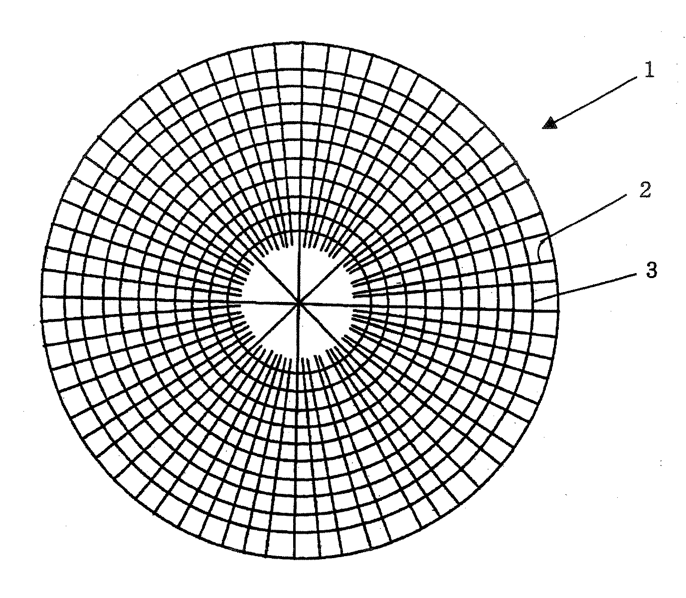
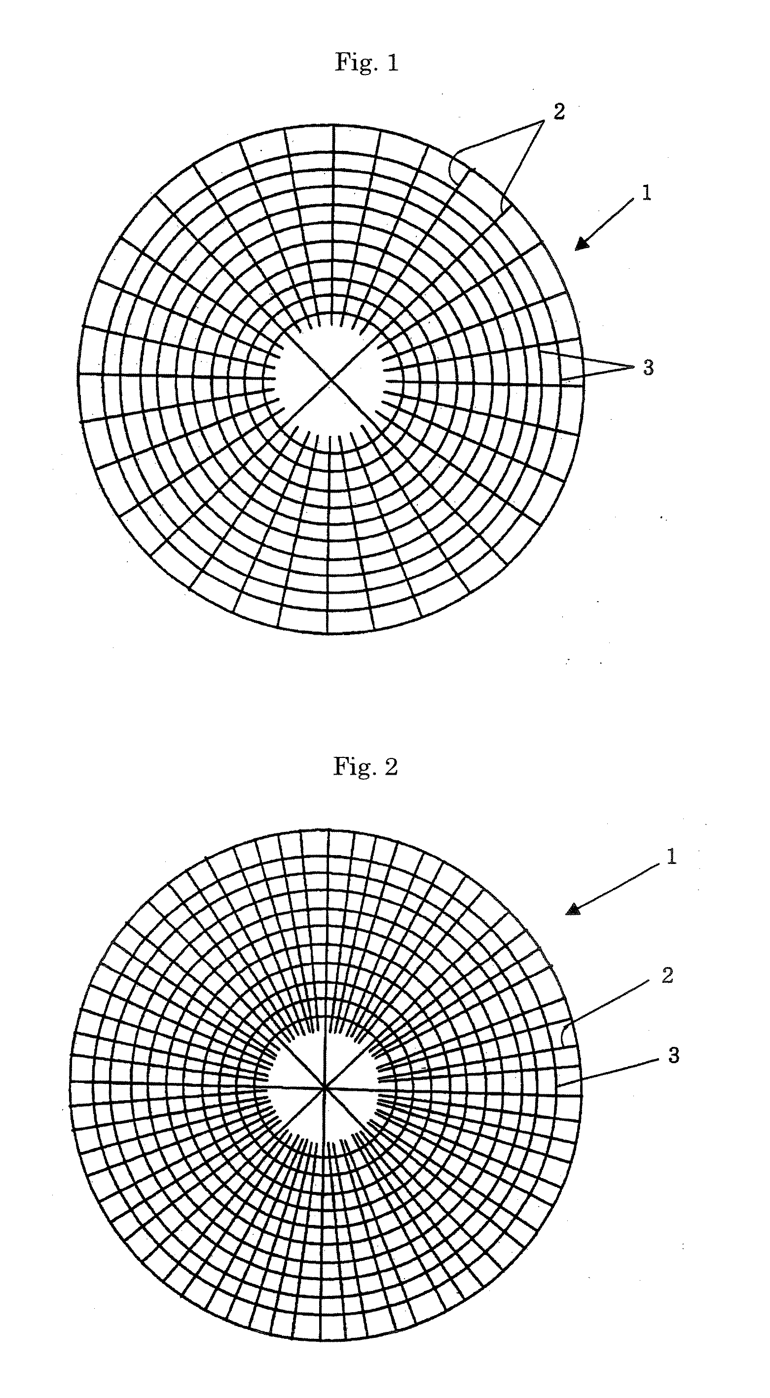
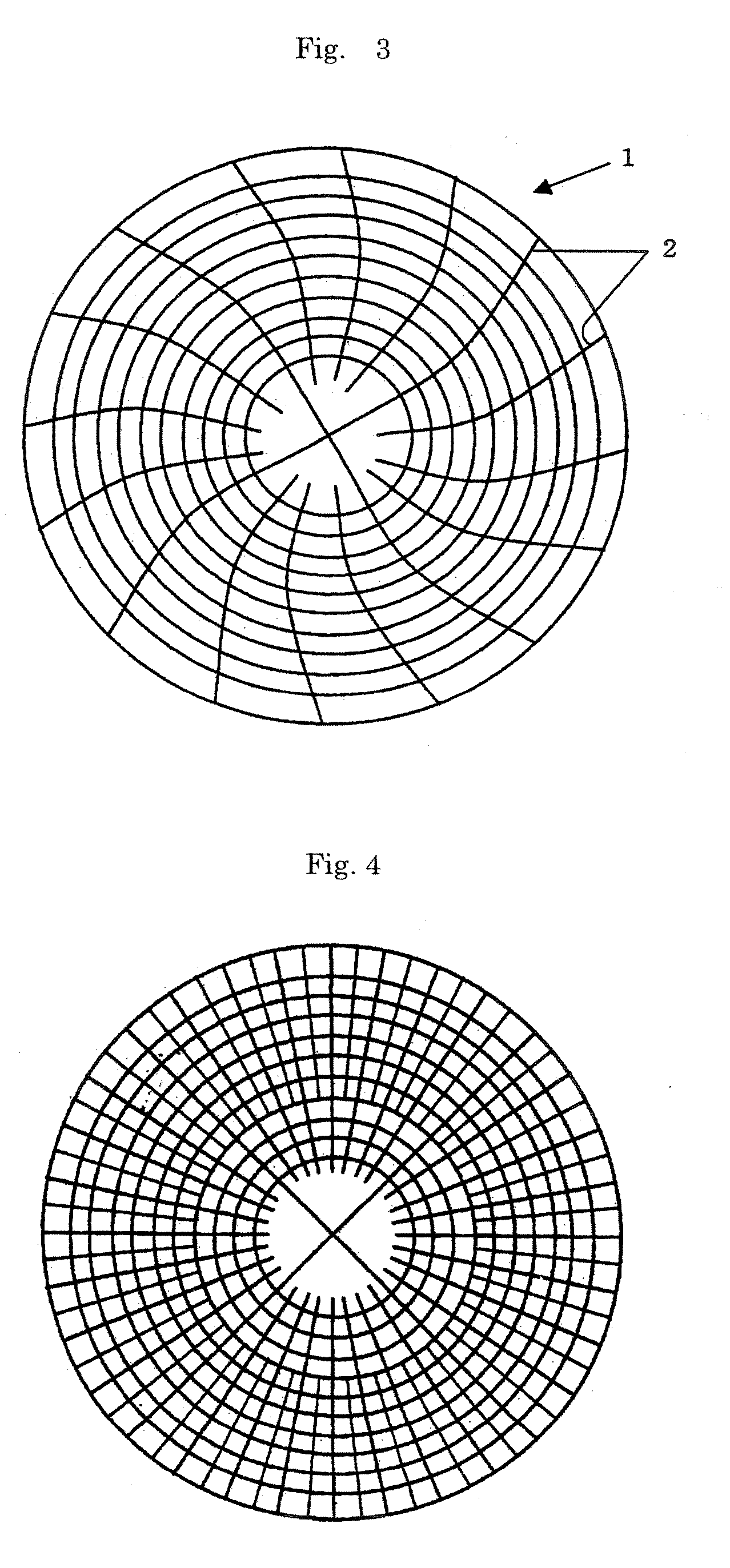
[0096] 80 parts by volume (equivalent to 72 parts by mass) of 1,2-polybutadiene (manufactured by JSR Corporation, trade name of “JSR RB830”) which would be crosslinked to become a water-insoluble matrix and 20 parts by volume (equivalent to 28 parts by mass) of β-cyclodextrin (manufactured by Bio Research Corporation of Yokohama, trade name of “Dexy Pearl β-100”, average particle diameter of 20 μm) as water-soluble particles were kneaded together by an extruder set at 160° C. Thereafter, 0.24 part by mass of dicumyl peroxide (manufactured by NOF Corporation, trade name of “Percumyl D”) was added to and kneaded with the above kneaded product at 120° C. to obtain a pellet. The resulting kneaded product was then heated in a metal mold at 170° C. for 18 minutes to be crosslinked so as to obtain a disk-like molded product having a diameter of 508 mm and a thickness of 2.8 mm. Concentrically circular grooves having a width of 0.5 mm, a...


PUM

PropertyMeasurementUnit
Widthaaaaaaaaaa
Distanceaaaaaaaaaa
Fractionaaaaaaaaaa

Abstract

A chemical mechanical polishing pad of the present invention has the following two groups of grooves on the polishing surface: (i) a group of first grooves intersect a single virtual straight light extending from the center toward the periphery of the polishing surface and have a land ratio represented by the following equation of 6 to 30:
Land ratio=(P−WW
(P is the distance between adjacent intersections between the virtual straight line and the first grooves, and W is the width of the first grooves); and (ii) a group of second grooves extend from the center portion toward the peripheral portion of the polishing surface and consist of second grooves which are in contact with one another in the area of the center portion and second grooves which are not in contact with any other second grooves in the area of the center portion. The chemical mechanical polishing pad of the present invention has a high polishing rate and excellent in-plane uniformity in the amount of polishing of the surface to be polished even when the amount of an aqueous dispersion for chemical mechanical polishing is made small.

Description

1. FIELD OF THE INVENTION [0001] The present invention relates to a chemical mechanical polishing pad and a chemical mechanical polishing method. 2. DESCRIPTION OF THE PRIOR ART [0002] In the manufacture of a semiconductor device, chemical mechanical polishing (generally abbreviated as CMP) is now often used as a polishing technique capable of forming an extremely flat surface for a silicon substrate or a silicon substrate having wirings and electrodes thereon. Chemical mechanical polishing is a technique for polishing by letting an aqueous dispersion for chemical mechanical polishing (aqueous dispersion containing abrasive grains dispersed therein) flow down over the surface of a chemical mechanical polishing pad while the polishing pad and the surface to be polished are brought into slide contact with each other. It is known that the polishing result is greatly affected by the shape and properties of the chemical mechanical polishing pad in this chemical mechanical polishing. A wi...

Claims


Application Information

Patent Timeline
IPC IPC(8): B24B7/30B24D11/00B24B37/26B24D99/00B24B37/30
CPCB24B37/26B24B37/30B24B37/00
Inventor NISHIMURA, HIDEKISHIMIZU, TAKAFUMIKURIYAMA, KEISUKETSUJI, SHOEI
Owner JSR CORPORATIOON
Why Eureka
Try Eureka