Communication system and method

a communication system and communication technology, applied in the field of ultra wideband (uwb), can solve the problems of limiting communication to distances of typically 5 to 20 meters, many applications will still experience problems or delays, and the transfer speed is less than acceptable for transferring a complete movie file between the first and the second. , to achieve the effect of large volumes of data to be transmitted in a very short period of tim

Inactive Publication Date: 2007-06-28
ITI SCOTLAND
View PDF11 Cites 7 Cited by
  • Summary
  • Abstract
  • Description
  • Claims
  • Application Information

AI Technical Summary

Benefits of technology

[0015] The concatenation of frequency sub-bands and the predetermined positional relationship between the two devices provides the advantage of enabling large volumes of data to be transmitted in a very short period of time.

Problems solved by technology

However, this has the limitation of limiting communication to distances of typically 5 to 20 meters.
Despite ultra-wideband having a large bandwidth that is capable of transmitting large amounts of data in a relatively short time, the ever increasing size of data downloads means that many applications will still experience problems or delays when copying large amounts of data between devices.
However, the transfer speed is less than acceptable for transferring a complete movie file between the first and second devices, which typically comprises transferring 10 to 40 GB of data.
However, such a system suffers from the disadvantage of requiring a plurality of transmitters and antennas, one for each of the concurrent sub-bands being used.
Therefore, the cost of both the transmitting and receiving devices is increased due to duplication of antenna and radio stages.

Method used


Image

  • Communication system and method
  • Communication system and method
  • Communication system and method

Examples


Embodiment Construction

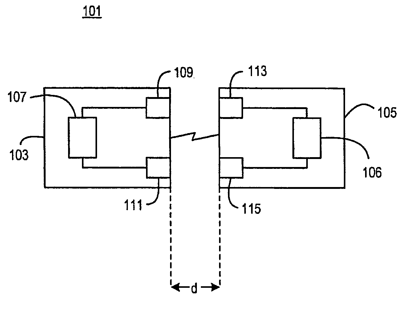
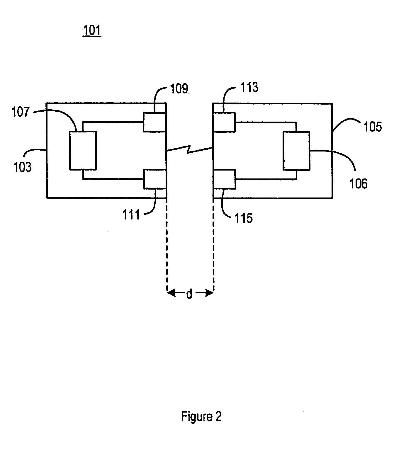
[0025]FIG. 2 shows a schematic view of an ultra-wideband communication system 101 according to the present invention. The ultra-wideband communication system 101 comprises a first communication device 103, such as a host device or server, which communicates with a second device 105, such as a portable device. It is noted that the second device 105 can be a “dumb” storage device such as a hard disc, or an “intelligent” device such a media player, mobile phone, or video playing device.

[0026] The first communication device 103 comprises a memory 107 for storing data that is to be downloaded to the second device 105. For example, the memory 107 can be adapted to store a catalogue or collection of movie films, audio tracks, photographic images, MP3 files, and so on. The first device 103 includes an ultra-wideband transmitter 109 for transmitting data over an air interface. Optionally, the first device 103 includes an ultra-wideband receiver 111 for receiving data from the second device ...


PUM


Abstract

An ultra-wideband communication system 101 comprises a first device 103, such as a host device or server, which communicates with a second device 105, such as a portable device. The first device 103 comprises a memory 107 for storing data, for example a movie, that is to be downloaded to the second device 105. The first device 103 includes an ultra-wideband transmitter 109 for transmitting data over an air interface to an ultra-wideband receiver 113 in the second device. The effective data transfer rate between the first device 103 and the second device 105 is increased by concatenating two or more frequency sub-bands in a multi-band orthogonal frequency division multiplexing scheme, such that the transmitter 109 in the first device 103 is configured to behave like a number of transmitters, all bursting at the same time. In addition, means are provided for enabling the second device 105 to be located in a fixed positional relationship with the first device 103 during the data transfer operation. The range of the ultra-wideband transmission is reduced significantly to a distance “d” which, in combination with the securing of multiple UWB sub-bands, enables the data throughput to be increased significantly. The distance “d” is less than 30 cm, and preferably touching (without electrical contact).

Description

FIELD OF THE INVENTION [0001] The invention relates to a communication system and method, and in particular to an ultra wideband (UWB) communication system and method for transferring a large amount of data, typically defined as greater than 1 GB, at high speed between a first communication device, such as a host device, and a second communication device, such as a portable device, in a wireless manner. BACKGROUND OF THE INVENTION [0002] Ultra-wideband is a radio technology that transmits digital data across a very wide frequency range, 3.1 to 10.6 GHz. It makes use of ultra low transmission power, typically less than −41 dBm / MHz, so that the technology can literally hide under other transmission frequencies such as existing Wi-Fi, GSM and Bluetooth. This means that ultra-wideband can co-exist with other radio frequency technologies. However, this has the limitation of limiting communication to distances of typically 5 to 20 meters. [0003] Ultra-wideband uses very short impulses, of...

Claims


Application Information

Patent Timeline
Patent Type & Authority Applications(United States)
IPC IPC(8): H04B7/00H04B1/69
CPCH04L27/2602H04L27/28H04L27/26H04L5/02
Inventor BREMNER, DUNCANEDWARDS, FRASER MURRAY
Owner ITI SCOTLAND
Why Eureka
Try Eureka