Catalyst system for reducing nitrogen oxide emissions

a catalyst system and nitrogen oxide technology, applied in the direction of physical/chemical process catalysts, metal/metal-oxide/metal-hydroxide catalysts, separation processes, etc., can solve the problems of no/sub>x /sub>x may be too expensive, environmental pollution, etc., and achieve the effect of reducing nox emissions of engines

Inactive Publication Date: 2007-06-28
GENERAL ELECTRIC CO
View PDF16 Cites 76 Cited by
  • Summary
  • Abstract
  • Description
  • Claims
  • Application Information

AI Technical Summary

Problems solved by technology

Production of emissions from mobile and stationary combustion sources such as locomotives, vehicles, power plants and the like, has resulted in environmental pollution.
This approach has resulted in the reduction of NOx over the years; however, the redesign approach requires a number of significant engine changes, and as a result is an expensive undertaking.
This method is disadvantageous in that potentially toxic chemicals such as ammonia may have to be carried on vehicles and maintained at sufficient levels for NOx reduction; moreover, an infrastructure of urea refueling stations would have to be built around the country to support vehicles, such as locomotives, using this approach.
For application on a locomotive or other mobile combustion sources, this method of reducing NOx may be too expensive and may take considerable space.
In certain cases the reductant is supplied by first “cracking” a portion of the hydrocarbon-based fuel (such as diesel fuel) to form lighter hydrocarbon species (along with some H2 and CO) suitable for use as reductants; this is done in the presence of a so-called “cracking catalyst.” Although effective in reducing the NOx emissions levels, this system also has certain disadvantages, such as the need to regenerate the cracking catalyst due to the build-up of coke and other byproducts of the cracking reaction, and the need for multiple reactor beds and other supporting system infrastructure to contain and support separate cracking and SCR catalyst materials.

Method used


Image

  • Catalyst system for reducing nitrogen oxide emissions
  • Catalyst system for reducing nitrogen oxide emissions

Examples


Embodiment Construction

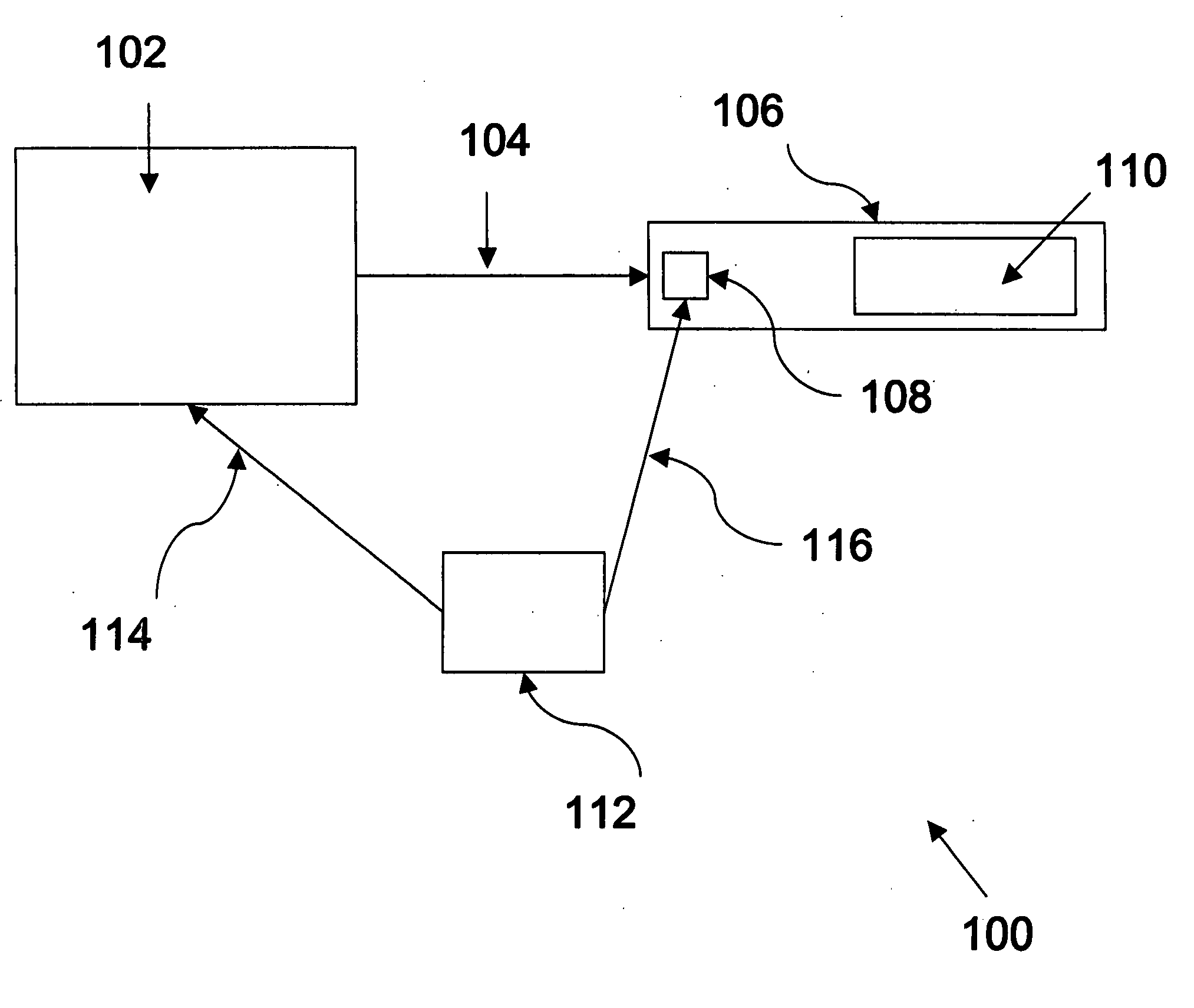
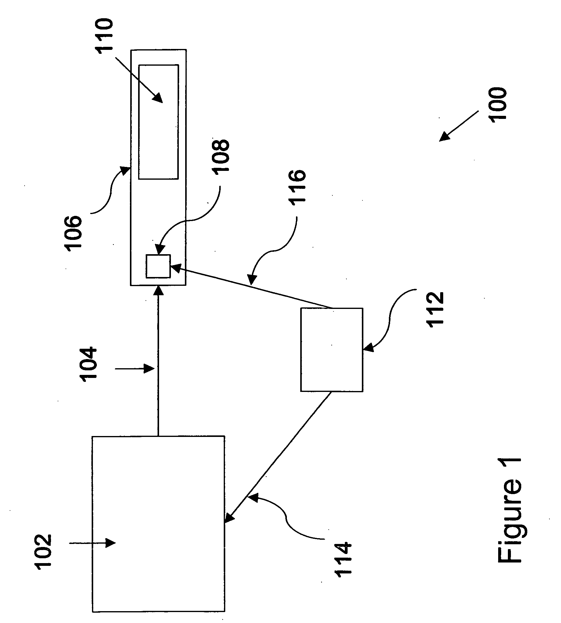
[0013] Embodiments of the present invention provide a more efficient alternative to more conventional reductant / SCR systems. Instead of using separate catalyst compositions to provide the fuel cracking function, the selective catalytic reduction (SCR) function, and, in some cases, other important functions, embodiments of the present invention provide for all such functions to occur efficiently in one catalyst formulation. Such high functionality may result in reduced costs, such as through the elimination of separate systems for fuel cracking, regeneration, and NOx reduction; moreover, the elimination of these system components may result in reduced weight and system footprint, which would prove advantageous for applications involving mobile systems such as locomotives and other vehicles or any other system with a space restriction.

[0014] In accordance with embodiments of the present invention, a catalyst system comprises a source of a fluid reductant and a multi-functional cataly...


PUM

PropertyMeasurementUnit
weight percentaaaaaaaaaa
sizeaaaaaaaaaa
molecular weightaaaaaaaaaa

Abstract

A multi-functional catalyst composition is provided. The multi-functional catalyst composition comprises a cracking catalyst material capable of enabling the conversion of the primary hydrocarbon into at least one secondary hydrocarbon having a lower molecular weight than the primary hydrocarbon, and a selective catalytic reduction (SCR) material capable of enabling the chemical reduction of NOx species. Further embodiments presented include a catalyst system comprising the catalyst, an apparatus for reducing NOx emissions comprising the catalyst system, and a method for making the catalyst material.

Description

BACKGROUND [0001] This invention relates to catalysts for reducing harmful exhaust emissions. More particularly, this invention relates to a multi-functional catalyst composition for reducing nitrogen oxide (NOx) emissions from engines that use hydrocarbon-based fuels, and to methods and systems for making and using such a composition. [0002] Production of emissions from mobile and stationary combustion sources such as locomotives, vehicles, power plants and the like, has resulted in environmental pollution. One particular source of such emissions is NOx emissions from vehicles. Environmental legislation restricts the amount of NOx that can be emitted by vehicles. In order to comply with this legislation, efforts have been directed at reducing the amount of NOx emissions. [0003] One method of emission reduction is directed to minimizing the amount of NOx emissions produced during the process of combustion in engines. This method generally involves redesigning engines to optimize the...

Claims


Application Information

Patent Timeline
Patent Type & Authority Applications(United States)
IPC IPC(8): B01J27/182B01J27/00B01J29/08B01J29/00B01J29/04B01J29/87B01J21/00
CPCB01D53/9418B01D2255/102B01D2255/104B01D2255/2065B01D2255/504B01J23/40B01J29/06B01J35/0006B01J37/0246Y02A50/20
Inventor LIU, KEMALE, JONATHANACHARYA, HARISH
Owner GENERAL ELECTRIC CO
Why Eureka
Try Eureka