Method and device for resilient seal system

a resilient seal and sealing technology, applied in the field of resilient seal systems, can solve the problems of water penetration, method may require additional time, high cost of pre-compressed tapes, etc., and achieve the effect of slowing down the deterioration at joints

Inactive Publication Date: 2007-07-05
ROBINSON STEVEN RICHARD
View PDF15 Cites 22 Cited by
  • Summary
  • Abstract
  • Description
  • Claims
  • Application Information

AI Technical Summary

Benefits of technology

[0013] In accordance with the present invention, a seal system and method are provided for slowing deterioration at joints or gaps and for providing a second seal having physical properties different from the first seal.

Problems solved by technology

Such pre-compressed tapes are expensive.
Another method is to combine the sealant and the pre-compressed foam tape; however such a method may require additional time because each joint must be coated with the sealant along its entire length, which may be five to seven feet, allowed to cure, then be compressed into the “precompressed” state for installation.
Major problems with seals include water penetration and contaminant penetration.
Water penetration may result in exposure of unsealed surfaces or in freezing expansion.
In the case of a seal where at least one panel contains wood, water penetration of the seal may result in rotting, particularly as the water may become trapped within the seal or gap.
In the case of a seal where at least one panel contains masonry, the water may penetrate into the masonry and expand when cooled below its freezing point, creating internal stresses on the masonry and potentially fracturing the masonry.
In all instances, penetration of water may result in further destruction of the seal should the water cool below its freezing point.
Contaminant penetration may also have detrimental effects on the gap or seal.
As the gap or seal is intended to permit expansion of the panels into the gap or seal, the presence of non-flexible contaminants may prevent such expansion and contribute to the increase of stresses and strains within the panels.
It is known that such flexing and conditions may have a detrimental effect on the seal between the panels.
Flexing may fatigue the sealant, which has limited flexibility and elasticity.
Weather conditions may alter the flexibility and elasticity of the sealant so as to result in cracking.
However the conditions which cause failure of the first seal layer may also cause the second substantially identical seal layer to fail.
Another difficulty in applying such sealants is to ensure that the sealant completely fills the gap or joint as it then exists and adequately attaches to the adjacent panels.
Increasing the nozzle size creates problems as the optimum nozzle size is the approximate width of the distance between adjacent panels at the lowermost portion of the gap or joint, which becomes difficult to reach with a full width nozzle.
Slowing the rate of application, while effective, slows the construction process, increases manpower requirements, and may require additional time for staging and scaffolding use, all of which are undesirable.
A further difficulty in apply such seals is that time necessary to apply multiple seal layers.
The second seal cannot be applied before the first seal has sufficiently cured as to prevent the seals from becoming intertwined or not allowing air required to cure and therefore transferring destructive forces between themselves.
Such conventional seals may require skilled labor, further consuming additional time.

Method used


Image

  • Method and device for resilient seal system
  • Method and device for resilient seal system

Examples


Embodiment Construction

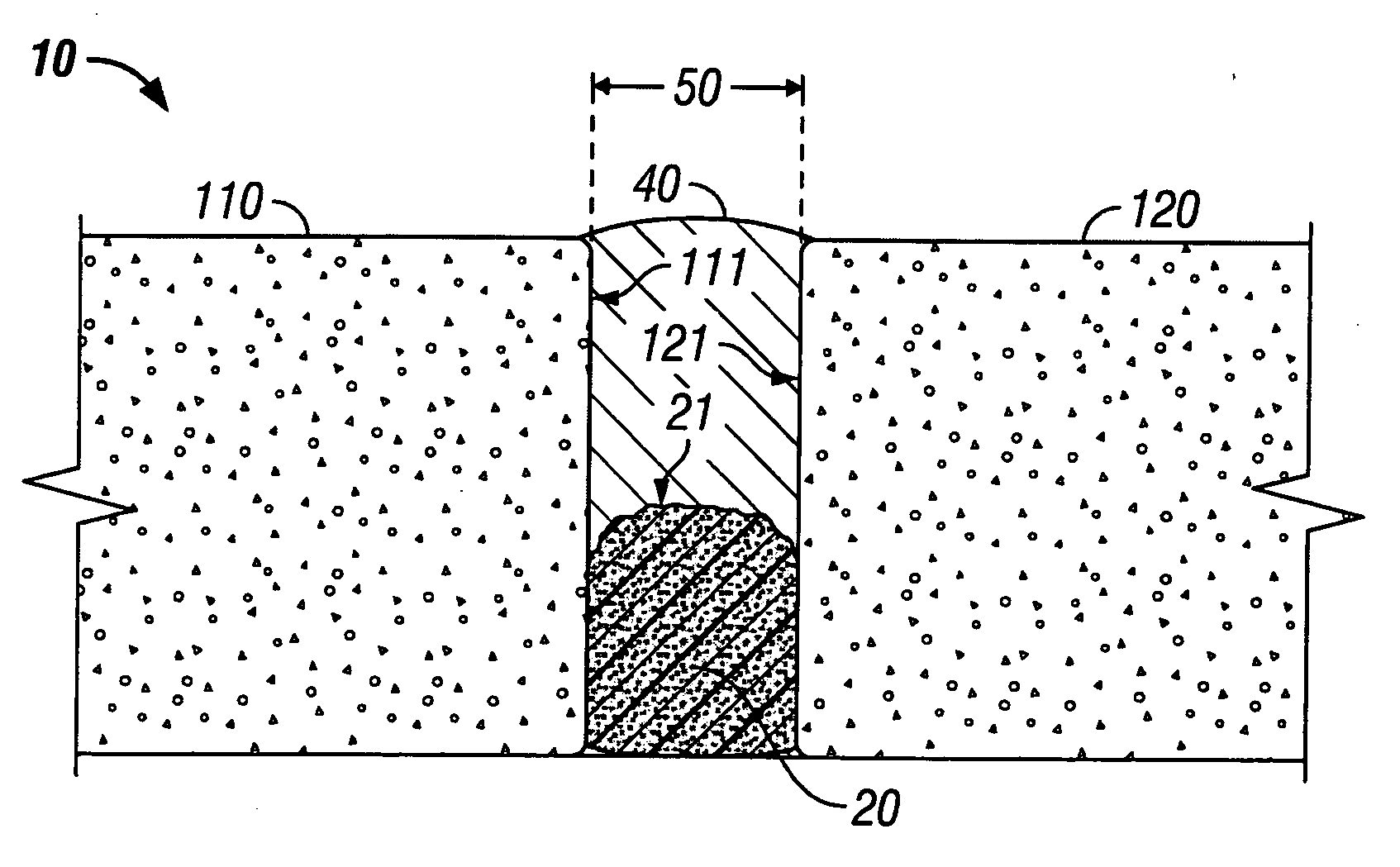
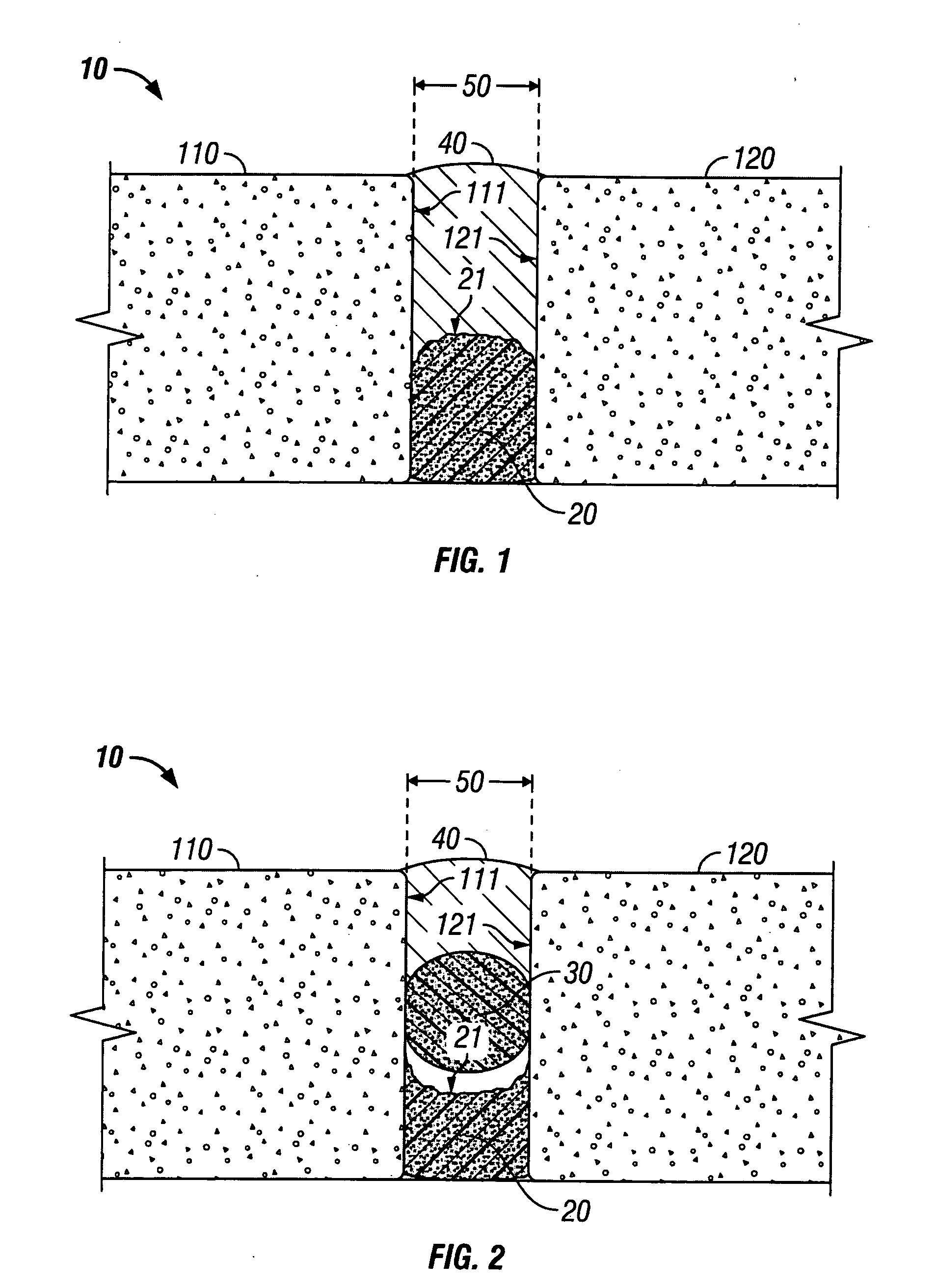
[0024] As shown in FIG. 1, the seal system 10 comprises of a foaming sealant 20 and a seal 40 applied between adjacent first panel 110 and second panel 120.

[0025] Foaming sealant 20 is a sprayed-in-place, elastic closed cell hydrophilic / phobic sealant that expands when exposed to air, is impermeable to water and cures rapidly. Because the foaming sealant 20 expands and fills the joint when dispensed, seal 40 may be applied almost immediately thereafter. In one embodiment foaming sealant 20 may be a polyurethane-based sealant. No hand working of foaming sealant 20 by the applicator is necessary once applied. Foaming sealant 20 expands upon contact with air / moisture and is applied in sufficient volume to expand to completely cover the distance between first panel 110 and second panel 120 and to adhere to first panel surface 111 and to second panel surface 121, forming a first resilient seal. Foaming sealant 20 is elastic, therefore not detaching from first panel surface 111 or from s...


PUM

PropertyMeasurementUnit
lengthaaaaaaaaaa
thicknessaaaaaaaaaa
expansive elasticaaaaaaaaaa

Abstract

A method and structure for providing a resilient seal system in the gap or joint between adjacent construction panels utilizing a foaming expansive elastic closed-cell liquid-impermeable sealant, a backer rod and a seal. The foaming expansive elastic closed-cell liquid-impermeable sealant is first introduced to the gap or joint between the adjacent construction panels. A seal is introduced into or over the gap after the foaming expansive elastic closed-cell liquid-impermeable sealant has sufficiently cured. In alternative embodiment a backer rod is located intermediate the sealant and seal as a spacing member.

Description

CROSS-REFERENCE TO RELATED APPLICATIONS [0001] Not Applicable. STATEMENT REGARDING FEDERALLY SPONSORED RESEARCH OR DEVELOPMENT [0002] Not Applicable. BACKGROUND OF THE INVENTION [0003] 1. Field of the Invention [0004] The present invention relates generally to systems and methods for creating a seal system between adjacent panels subject to temperature expansion and contraction. More particularly, the present invention is directed to providing seals in construction joints that are resilient, and ideally waterproof, over relatively long periods of time. [0005] 2. Description of the Related Art [0006] Construction panels come in many different sizes and shapes and may be used for various purposes, including roadways, sideways, and pre-cast structures. In many situations it is necessary to form a lateral gap or joint in the structure to allow for independent movement of the adjacent sections. Such movement is caused by many factors including expansion and contraction of the adjacent se...

Claims


Application Information

Patent Timeline
Patent Type & Authority Applications(United States)
IPC IPC(8): E01C11/08E04B1/68
CPCE04B1/6801E01C11/10
Inventor ROBINSON, STEVEN RICHARD
Owner ROBINSON STEVEN RICHARD
Why Eureka
Try Eureka