Water injection manifold pressure relief vent

Inactive Publication Date: 2007-07-05
GENERAL ELECTRIC CO
View PDF11 Cites 3 Cited by
  • Summary
  • Abstract
  • Description
  • Claims
  • Application Information

AI Technical Summary

Benefits of technology

[0008]The pressure relief system may include a pressure transducer and an orifice plate positioned on the pressure relief line. The relief valve may include a solenoid valve. The pressure relief system may include a drain. The pressure relief line may include a position about a top of the water manifold. The pressure relief line may include a position adjacent to the manifold so as to reduce the volume of trapped air therein.
[0010]The present application further describes a method for relieving the water pressure within a water manifold positioned about a combustor of a gas turbine during a load rejection. The method may include closing a stop valve assembly on an incoming water source in communication with the water manifold, opening a relief valve on a pressure relief line in communication with the water manifold, and draining the water within the water manifold via the pressure relief line. The relief valve may be open before the stop valve assembly is completely closed. The step of opening the relief valve prevents water from being injected into the combustor. The step of opening the relief valve further purges the pressure relief line of trapped air.
[0012]The pressure relief system may include an orifice plate. The relief valve may include a solenoid valve. The relief line may include a position about a top of the water manifold. The pressure relief line also may include a position adjacent to the manifold so as to reduce the volume of trapped air therein.

Problems solved by technology

Exhaust emissions from the hot combustion gases generally are a concern and may be subjected to mandated limits.
Water injection manifold pressure reduction, however, may not always be fast enough to reduce the possibility of a flameout, i.e., the water already in the manifold may continue to flow into the combustor.
The increased reaction time should limit the possibility of flameout and the associated restart expenses.

Method used


Image

  • Water injection manifold pressure relief vent
  • Water injection manifold pressure relief vent

Examples


Embodiment Construction

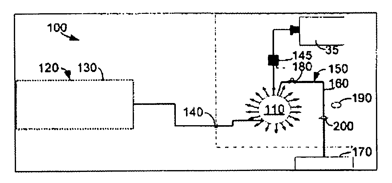
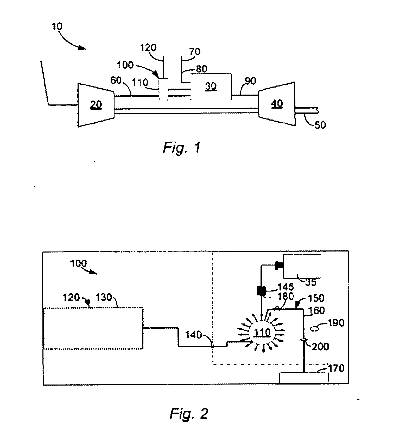
[0016]Referring now to the drawings in which like numerals refer to like elements throughout the several views, FIG. 1 shows a turbine engine 10. The turbine engine 10 may include a compressor 20 disposed in serial flow communication with a low NOx combustor 30 and a turbine 40. As described above, the combustor 30 may take the form of a number of burner cans 35 positioned in a largely circular shape. Other types of combustors 30 may be used herein. The turbine 40 may be coupled to the compressor 20 via a drive shaft 50. The drive shaft 50 may extend from the turbine 40 for powering an electrical generator (not shown) or any other type of desired external load.

[0017]During operation as described above, the compressor 20 discharges a compressed airflow 60 into the combustor 30. A fuel injector 70 likewise may deliver a fuel flow 80 to the combustor 30 for mixing therein. The compressed airflow 60 and the fuel flow 80 are combusted in the combustor 30 to create a combustion gas stream...


PUM


Abstract

A water injection system positioned about a combustor of a gas turbine engine. The water injection system may include a water manifold and a pressure relief system in communication with the water manifold. The pressure relief system may include a relief vent positioned on a pressure relief line.

Description

TECHNICAL FIELD[0001]The present application relates generally to gas turbine engines and more particular relates to a water pressure relief system for a water manifold used with a combustor of a gas turbine engine.BACKGROUND OF THE INVENTION[0002]Gas turbine engines generally include a compressor for compressing an incoming air stream. The air stream is mixed with fuel and ignited in a combustor for generating hot combustion gases. The combustion gases in turn flow to a turbine. The turbine extracts energy from the combustion gases for driving a turbine shaft. The turbine shaft powers the compressor and generally an external load such as an electrical generator.[0003]Exhaust emissions from the hot combustion gases generally are a concern and may be subjected to mandated limits. Certain types of gas turbine engines are designed for low exhaust emissions operation, and, in particular, for low NOx (nitrogen oxides) operation. Low NOx turbine engines generally include a combustor in th...

Claims


Application Information

Patent Timeline
IPC IPC(8): F02C3/30
CPCF01D21/02F02C3/30F05D2260/212F05D2260/602F02C3/305Y10T137/0396
Inventor ALEXANDER, MICHAEL J.ESTRADA, KELVIN R.PIMPLIKAR, ROHAN SHARADIASILLO, ROBERT J.
Owner GENERAL ELECTRIC CO
Why Eureka
Try Eureka