Refrigeration cycle apparatus

a technology of refrigeration cycle and apparatus, which is applied in the direction of mechanical apparatus, lighting and heating apparatus, refrigeration components, etc., can solve the problem that the refrigerant flowing through the circuit that bypasses the expander does not contribute to any improvement in system efficiency, so as to achieve the effect of improving the overall performance of the refrigeration cycle apparatus and avoiding the constant density ratio

Inactive Publication Date: 2007-07-05
PANASONIC CORP
View PDF3 Cites 42 Cited by
  • Summary
  • Abstract
  • Description
  • Claims
  • Application Information

AI Technical Summary

Benefits of technology

[0025] According to the present invention as described above, by allowing the refrigerant to flow through the bypass circuit, the refrigerant flow rate through the radiator can be increased while the constraint of constant density ratio is avoided. Therefore, the overall performance of the refrigeration cycle apparatus can be improved.

Problems solved by technology

However, a problem has been that the refrigerant flowing through the circuit that bypasses the expander does not contribute to improvements in system efficiency at all.

Method used


Image

  • Refrigeration cycle apparatus
  • Refrigeration cycle apparatus
  • Refrigeration cycle apparatus

Examples


first embodiment

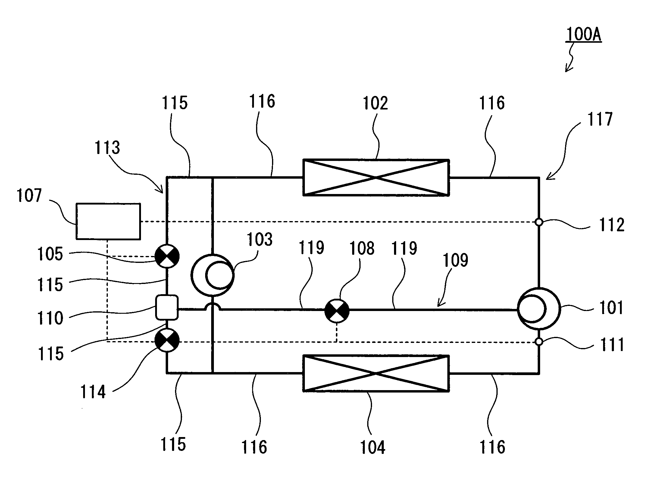
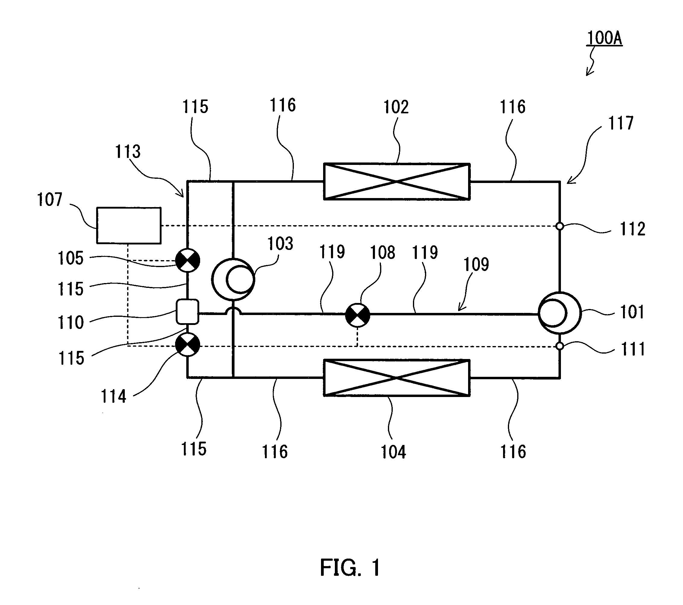
[0039]FIG. 1 is a configuration diagram illustrating a refrigeration cycle apparatus according to a first embodiment of the present invention. A refrigeration cycle apparatus 100A of the present embodiment is furnished with a compressor 101 for compressing a refrigerant such as hydrofluorocarbon or carbon dioxide, a radiator 102 for cooling the refrigerant compressed by the compressor 101, an expander 103 for decompressing and expanding the refrigerant cooled by the radiator 102 and recovering mechanical power from the refrigerant under expansion, an evaporator 104 for heating the refrigerant decompressed by the expander 103, and a plurality of main pipes 116 (main conduits) for connecting the compressor 101, the radiator 102, the expander 103, and the evaporator 104 in that order. The compressor 101, the radiator 102, the expander 103, the evaporator 104, and the main pipes 116 constitute a main circuit 117 through which the refrigerant circulates.

[0040] In the first embodiment, t...

second embodiment

[0064] The first embodiment has described the case in which the injection circuit 109 is connected directly to the compressor 101. By contrast, the refrigeration cycle apparatus according to the second embodiment differs from the first embodiment in that it has a plurality of compressors. It should be noted, however, that the advantageous effects achieved by the bypass circuit and the injection circuit are common between the second embodiment and the first embodiment.

[0065] As illustrated in FIG. 6, a refrigeration cycle apparatus 100B of the second embodiment is furnished with a low-pressure-side compressor 101A, and a high-pressure-side compressor 101B connected in series with the low-pressure-side compressor 101A via one of the main pipes 116. Specifically, a multi-stage compressor including the low-pressure-side compressor 101A and the high-pressure-side compressor 101B is employed as the compressor for compressing a refrigerant. In this case, the intermediate pressure portion ...

third embodiment

[0067]FIG. 7 illustrates a configuration diagram of a refrigeration cycle apparatus according to a third embodiment. A refrigeration cycle apparatus 100C shown in FIG. 7 differs from that of the first embodiment in that an injection circuit 109′ further includes an injector 123 provided downstream from the second flow rate control valve 108. In other respects, the present embodiment is similar to the first embodiment, and in the drawings, the same reference numerals designate the same components.

[0068] The injector 123 in the injection circuit 109′ is capable of switching between an open state that permits passage of the refrigerant (gas refrigerant) and a closed state that inhibits passage of the refrigerant, and it may be, for example, a solenoid valve controlled by the controller 107. Thus, the present embodiment makes it possible to control even the timing of injecting the gas refrigerant into the intermediate pressure portion of the compressor 101. For example, by controlling ...


PUM


Abstract

A refrigeration cycle apparatus includes a compressor, a radiator, an expander, an evaporator, a bypass circuit, and an injection circuit. The bypass circuit has a flow rate control valve and a gas-liquid separator. One end of the bypass circuit is connected to an intake conduit of the expander and the other end thereof is connected to a discharge conduit of the expander so that a portion of refrigerant passed through the radiator bypasses the expander and is guided to the flow rate control valve and that the liquid refrigerant separated by the gas-liquid separator returns to the discharge conduit of the expander. One end of the injection circuit is connected to a gas outlet portion of the gas-liquid separator and the other end thereof is connected to an intermediate pressure portion of the compressor.

Description

BACKGROUND OF THE INVENTION [0001] 1. Field of the Invention [0002] The present invention relates to a refrigeration cycle apparatus applied to hot water heaters, air-conditioners, and the like, and more particularly to a configuration and a control method therefor that achieve high efficiency by mixing a refrigerant that flows through a bypass circuit with a refrigerant that is in the process of compression. [0003] 2. Description of Related Art [0004] A known refrigeration cycle apparatus uses a fluid machine in which both a positive displacement compressor and a positive displacement expander are coupled uniaxially so that the energy of expansion of the refrigerant recovered by the expander can be used as auxiliary driving power for the compressor. In this kind of refrigeration cycle apparatus, the compressor and the expander constantly rotate at the same frequency. Unless some special mechanism is provided, the intake capacity of the compressor and the intake capacity of the expa...

Claims


Application Information

Patent Timeline
Patent Type & Authority Applications(United States)
IPC IPC(8): F25B41/00F25B1/00
CPCF25B1/04F25B1/10F25B9/06F25B2309/06F25B2341/0662F25B2700/21152F25B2400/14F25B2400/23F25B2600/2509F25B2600/2515F25B2700/21151F25B2400/13F25B41/39
Inventor YAKUMARU, YUUICHIKOMORI, KOUTAMURA, TOMOICHIROHONMA, MASAYA
Owner PANASONIC CORP
Why Eureka
Try Eureka