Gas-drying system

a technology of gas dryer and construction, which is applied in the direction of defrosting, separation processes, and domestic cooling apparatus, can solve the problems of limiting the range of application and performance of devices, the inability to optimize the system package size and cost of the customer, and the saturated gas, whether at elevated or reduced temperature, so as to reduce the conduction between the recuperator and the refrigerated section. , the effect of eliminating external plumbing

Inactive Publication Date: 2007-07-05
FLATPLATE INC
View PDF31 Cites 9 Cited by
  • Summary
  • Abstract
  • Description
  • Claims
  • Application Information

AI Technical Summary

Benefits of technology

[0027] An advantage of the present invention is that it eliminates external plumbing between the separator and the heat exchanger sections.
[0028] Another advantage of the present invention is that conduction between the recuperator and refrigerated sections is substantially reduced.
[0029] A further advantage of the present invention is that the number of heat exchanger plates for the recuperator and refrigerated sections can differ with respect to each other.
[0030] A yet further advantage of the present invention is that it can withstand elevated fluid pressure levels.
[0031] A still yet further advantage of the present invention is that it has fewer different parts.
[0032] Other features and advantages of the present invention will be apparent from the following more detailed description of the preferred embodiment, taken in conjunction with the accompanying drawings which illustrate, by way of example, the principles of the invention. Corresponding reference characters indicate corresponding components throughout the several views of the drawings. Skilled artisans will appreciate that elements in the figures are illustrated for simplicity and clarity and have not necessarily been drawn to scale. For example, the dimensions of some of the elements in the figures may be exaggerated relative to other elements to help to improve understanding of various embodiments of the present invention. Also, common but well-understood elements that are useful or necessary in a commercially feasible embodiment are typically not depicted in order to facilitate a less obstructed view of these various embodiments of the present invention.

Problems solved by technology

Saturated gas, whether at elevated or reduced temperature, is typically unsuitable for many industrial applications.
However, there are several significant drawbacks associated with this integral construction.
Second, the design construction requires several differently sized stamped plates to cover a typical performance range of industrial interest.
Third, the “footprint” size of the integral construction cannot be adjusted to optimize the customer's system package size and cost because the recuperator and refrigerated dryer sections must have the same number of plates, respectively.
Fourth, a further disadvantage resulting from the recuperator and refrigerated dryer sections having the same number of plates is that the refrigerated dryer section cannot be changed or independently adjusted, which greatly restricts the range of application and performance of the device.
Fifth, the integral construction design has significantly lowered pressure-bearing capabilities because the separator section is attached, and therefore only supported on one side by the recuperator or refrigerated dryer section.
Sixth, the integral construction, as well as the construction as shown in FIG. 2, both suffer from a lower thermal efficiency caused by the recuperator section being directly coupled to the refrigerated dryer section.
In other words, since the recuperator section operates at a higher average temperature than the refrigerated dryer section, heat is transferred from the recuperator to the refrigerated dryer section, which increases the thermal load required from the refrigeration system, and reduces the re-heat temperature of the dry gas that exits the recuperator.

Method used


Image

  • Gas-drying system
  • Gas-drying system
  • Gas-drying system

Examples


Embodiment Construction

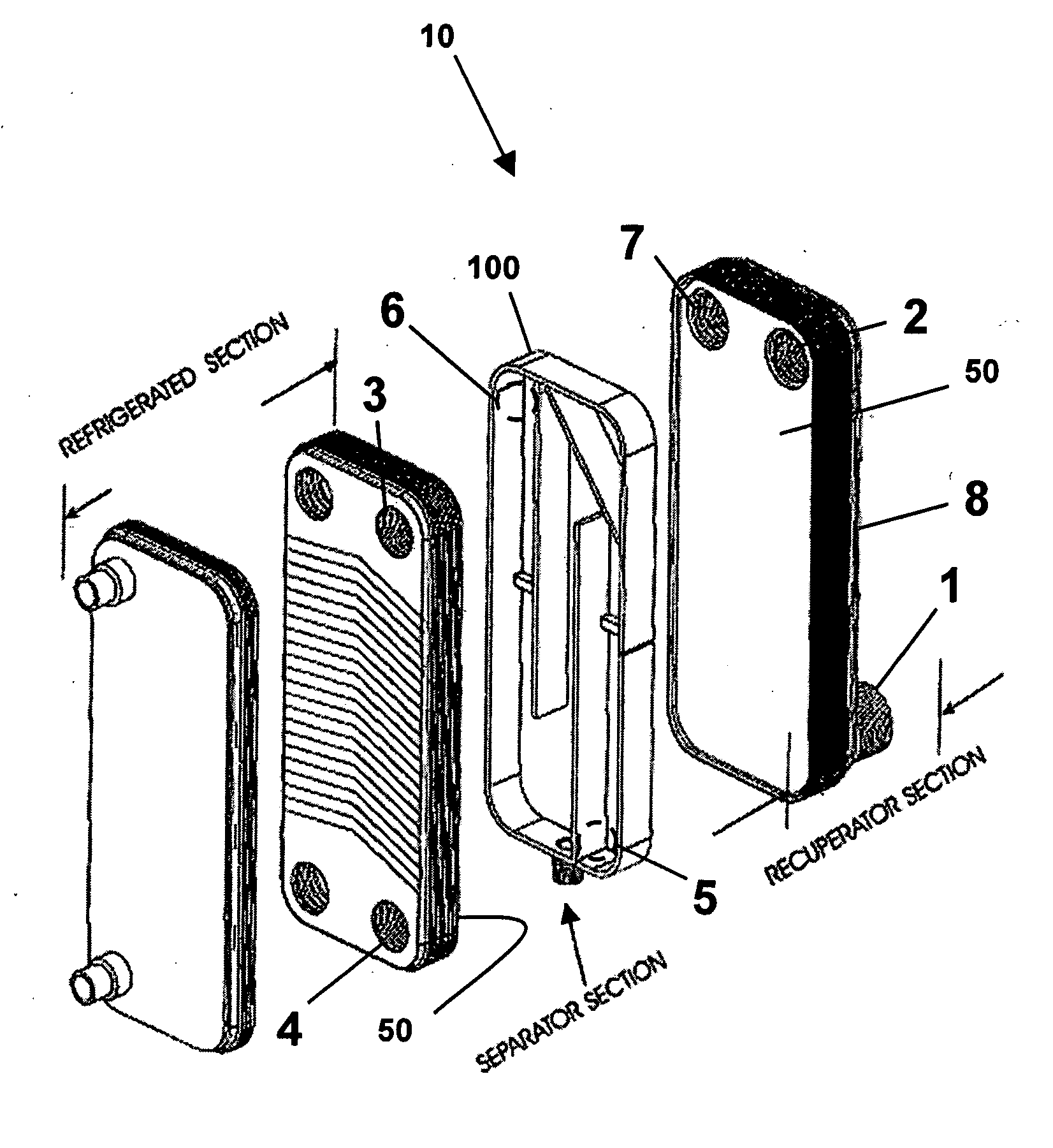
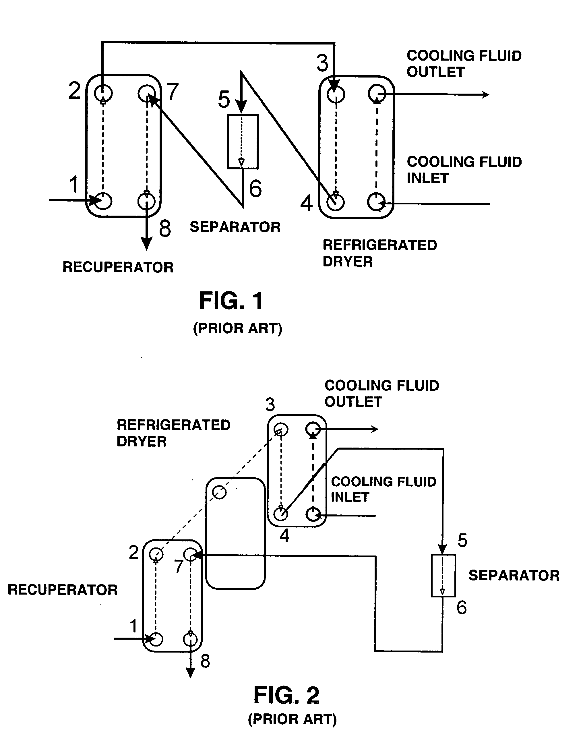
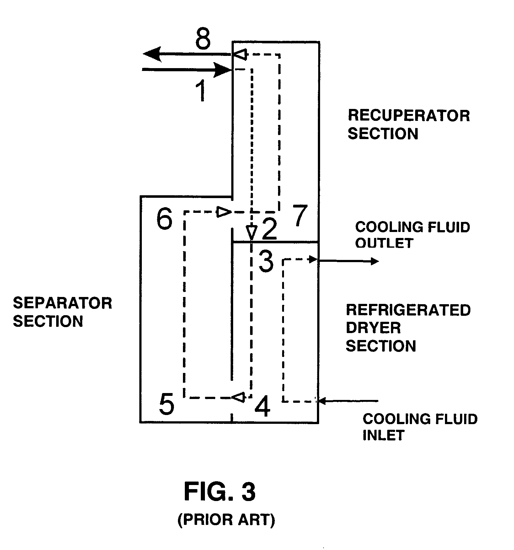
[0040] One embodiment of a gas dryer 10 of the present invention is depicted in FIG. 5. As shown schematically in FIG. 4, a gas to be dried or non-processed gas enters Port 1 of a recuperator section or recuperator and flows from Port 1 to Port 2 along a fluid flow path formed in the recuperator that is not in fluid communication, but in thermal communication via a conductive barrier 185 with a second fluid flow path defined between Ports 7 and 8. Upon flowing past Port 2, the gas flows through a partitioned opening 155 formed in a moisture separator section or separator. After flowing through the separator, the gas enters Port 3 of a refrigerated dryer section or refrigerated dryer and flows from Port 3 to Port 4 along a fluid flow path formed in the refrigerated dryer that is not in fluid communication, but in thermal communication via a conductive barrier 190 with a second fluid flow path through which a separate cooling fluid is circulated. The cooling fluid cools the gas to abo...


PUM

PropertyMeasurementUnit
angleaaaaaaaaaa
temperatureaaaaaaaaaa
forcesaaaaaaaaaa

Abstract

An apparatus and method for a gas drying system includes a recuperator section having first and second fluid flow paths wherein fluid flowing through the first fluid flow path is in thermal communication with fluid flowing through the second fluid flow path. A refrigerated section having a third fluid flow path is in fluid communication with the first fluid flow path for further cooling the flowing fluid to about a dew point temperature. A moisture separator section is disposed between the recuperator and refrigerated sections, the assembled sections forming an integral construction, wherein the separator is in planar contact with the recuperator and refrigerated sections. The separator has a fourth fluid flow path in fluid communication with the third fluid flow path and the second fluid flow path for removing condensed and entrained liquid from a stream of flowing fluid prior to fluid flowing into the second fluid flow path.

Description

FIELD OF THE INVENTION [0001] The present invention is directed to a gas dryer construction, and more particularly, the present invention is directed to an integral plate-type gas dryer construction. BACKGROUND OF THE INVENTION [0002] Gas-drying systems are used to remove moisture from gases, such as air, methane, and carbon dioxide. Moisture removal is typically achieved either by passing the moist gas through a desiccant or by flowing it over a heat exchanger surface that is maintained at a lower temperature than the flowed gas. Heat exchanger type gas dryers are typically much more compact than desiccant types gas dryers, and primarily for that reason, are more prevalent in the industry. Moreover, heat exchanger type gas dryers utilizing stacked plates provide yet further reductions in the size of the heat exchanger. [0003] Typically, gas dryer heat exchangers utilize either a low temperature refrigerant, produced by a mechanical refrigeration cycle, or a low temperature fluid, s...

Claims


Application Information

Patent Timeline
Patent Type & Authority Applications(United States)
IPC IPC(8): F28F13/18F28F3/00F25D21/00F25D21/14
CPCB01D5/0015F28D9/0075B01D53/265B01D5/009
Inventor BOGART, JAMES E.
Owner FLATPLATE INC
Why Eureka
Try Eureka