Cash recycling system having a cash receiving unit and a cash dispensing unit

a cash recycling and cash dispensing technology, applied in automatic teller machines, atm details, instruments, etc., can solve the problems of many manual transactions, mismatch in denomination distribution between, and high labor intensity in the direction of cash recycling, etc., to reduce manual labor, high operational reliability and throughput, and operate safely and efficiently

Inactive Publication Date: 2007-07-05
SCAN COIN IND AB
View PDF76 Cites 26 Cited by
  • Summary
  • Abstract
  • Description
  • Claims
  • Application Information

AI Technical Summary

Benefits of technology

[0012] An object of the invention is to solve or at least mitigate the problems associated with the prior art as described above. In particular, the invention seeks to provide a cash recycling system which operates safely and efficiently, with high operational reliability and throughput, and with reduced manual labor.

Problems solved by technology

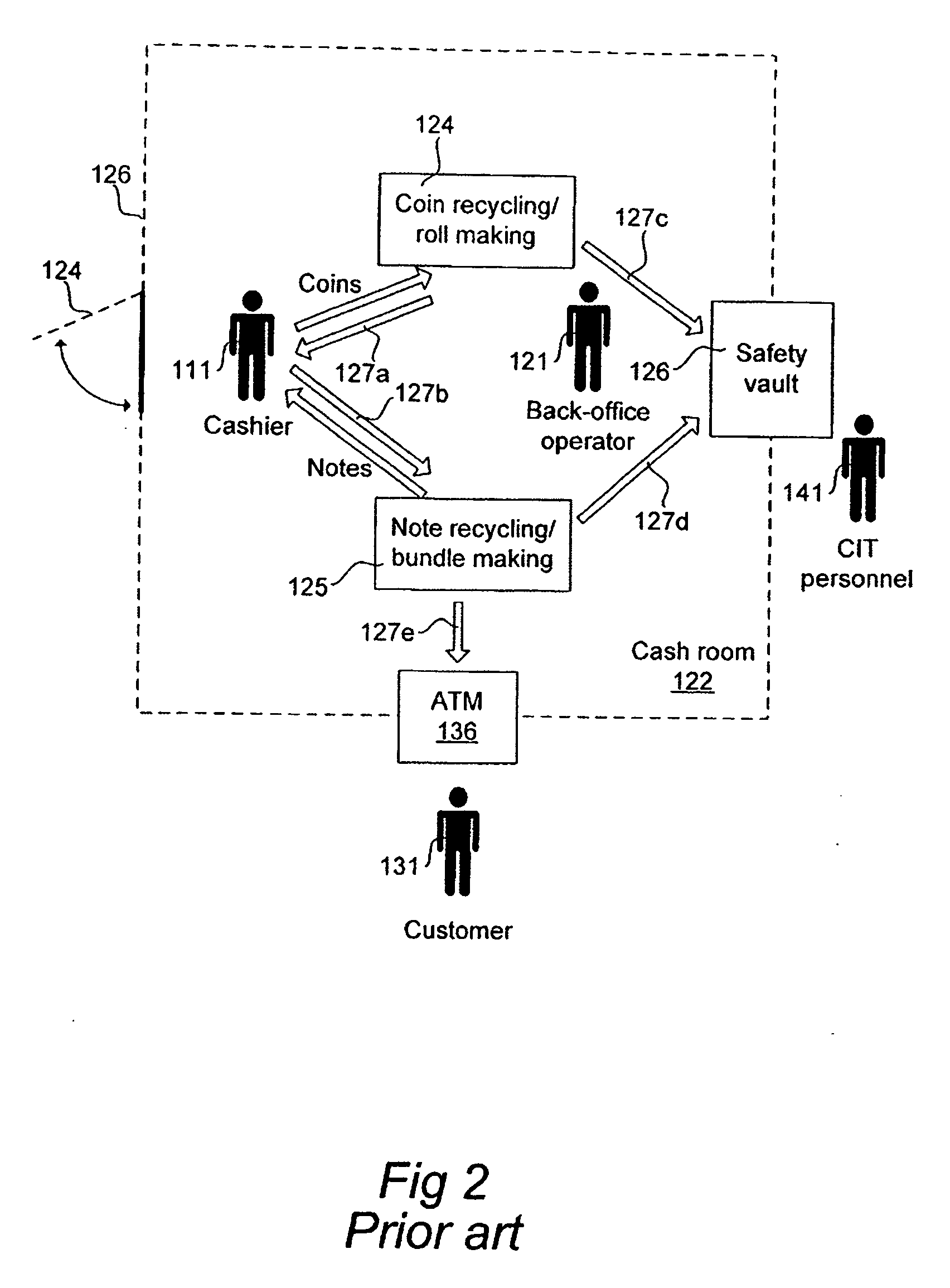
Even if access to this door is restricted by way of a key, magnetic card, personal code, etc, there are evident safety risks both as regards the honesty of the cashier 111 himself and the risk that a foreign person may force the cashier 111 to open the cash room 122.
Another disadvantage is that the approach is labor-intensive, involving many manual transactions 127a-e for both cashier 111 and back-office operator 121.
Another drawback with this alternative is that the automatic merchant teller machine 123 will often be a bottle-neck in the cash handling; imagine for instance 10 cashiers starting or ending their work shift at the same time and all needing to use the automatic merchant teller machine 123.
However, a problem experienced with such a single cash recycling apparatus in practical applications is that there will often be a mismatch in denomination distribution between cash deposited by users and cash that users want to collect.
Thus, in effect, a shortage of small-value coins and an abundance of large-value coins will quickly develop in a single cash recycling apparatus, therefore requiring intervention by CIT company or back-office operator for relieving the cash recycling apparatus of excessive large-value coins and replenishing small-value coins as needed.
In addition, a single cash recycling apparatus will still suffer from the bottle-neck problem described above.

Method used


Image

  • Cash recycling system having a cash receiving unit and a cash dispensing unit
  • Cash recycling system having a cash receiving unit and a cash dispensing unit
  • Cash recycling system having a cash receiving unit and a cash dispensing unit

Examples


Embodiment Construction

[0032]FIG. 4 illustrates a cash room 222 with a cash recycling system according to one embodiment. Elements in FIGS. 4 and 2 which are identical, similar or equivalent to each other are represented by reference numerals with the last two digits in common. As seen in FIG. 4, the cash recycling system consists of a cash receiving unit 228 and a cash dispensing unit 229. FIG. 5 illustrates these two units in more detail as schematic block diagrams. The cash receiving unit 228 and cash dispensing unit 229 are mounted in a through-the-wall manner (e.g., at least partially received in respective openings in a wall 226 that surrounds the cash room 222), so that a front side 203a, 203b (i.e., a cashier side) of each unit faces outwardly from the wall 226, and whereas a rear side 205a, 205b (i.e., a service side) of each unit is located on the inside of the cash room 222. In this manner, cashiers 211a,b will have access to the front sides 203a, 203b of units 228, 229 but not to their rear si...


PUM


Abstract

A cash recycling system is presented which has a cash receiving unit, the cash receiving unit has a cash input module, a cash processor, a cash output module, and a cash dispensing unit. The cash dispensing unit has a cash input module, a cash processor, and a cash output module. The cash input module of the cash receiving unit and the cash output module of the cash dispensing unit are accessible to a first type of user. The cash dispensing unit and the cash receiving unit are physically separate from and operative independently of each other. The cash output module of the cash receiving unit is adapted to supply cash, as processed by the cash processor, in a form which is sorted in denomination and therefore directly suitable for loading into the cash input module of the cash dispensing unit.

Description

CROSS-REFRENCE TO RELATED APPLICATION [0001] This application is a continuation of International Application No. PCT / SE2005 / 001120, filed Jul. 6, 2005 and designationg the United States, which claims priority to Swedish Patent Application No. 0401774-5, filed Jul. 6, 2004 and U.S. Provisional Patent Application No. 60 / 585,909, filed on Jul. 7, 2004. INCORPORATION BY REFERENCE [0002] The specification and drawings of International Application No. PCT / SE2005 / 001120, filed Jul. 6, 2005, the specificaiton and drawings of Swedish patent application no. 0502492-2, filed on Nov. 11, 2005 and the specification and drawings of U.S. provisional patent application No. 60 / 736,601, filed on Nov. 14, 2005, are incorporated herein in their entirety, by this reference.FIELD OF THE INVENTION [0003] The present invention relates to cash recycling, and more specifically to a cash recycling system which is particularly useful at commercial premises with plural stations for cash payment. TECHNICAL BACKG...

Claims


Application Information

Patent Timeline
Patent Type & Authority Applications(United States)
IPC IPC(8): G07F7/04G07D
CPCG07D1/02G07D3/00G07F19/20G07F19/205G07F19/202G07F19/203G07F19/201G07D11/16G07D11/009G07F19/00
Inventor BRANDSTROM, MICHAELSJOSTROM, ANDERSKARLSSON, JERRYANDERSON, KJELLMALMGREN, LARS
Owner SCAN COIN IND AB
Why Eureka
Try Eureka