Achieving accurate time-of-flight calibrations with a stationary coincidence point source

a point source and coincidence technology, applied in the field of medical imaging systems, can solve the problems of introducing various time delays into light signals, affecting the accuracy of time-of-flight calibration, so as to achieve accurate calibration and refine calibration. the effect of the delay tim

Active Publication Date: 2007-07-05
KONINKLIJKE PHILIPS ELECTRONICS NV
View PDF13 Cites 32 Cited by
  • Summary
  • Abstract
  • Description
  • Claims
  • Application Information

AI Technical Summary

Benefits of technology

[0008] One advantage includes accurately calibrating detector delay times for a TOF-PET scanner with a stationary source.
[0009] Another advantage lies in using scatter radiation to calibrate detector delay times for a TOF-PET scanner.
[0010] Another advantage resides in using a combination of scatter and 180 degree opposite coincident radiation to provide a refined calibration for a TOF-PET scanner.

Problems solved by technology

However, there are time variations amongst scintillation crystals as to how quickly the radiation is converted into light, which introduces various time delays into the light signals.
Further time delays are introduced due to the conversion of the light into electrical signals.
Such time delays typically vary from conversion device to conversion device.
Conventional time-delay calibration techniques tend to be complicated and use a large number of data channels, typically tens of thousands of channels.
This calibration procedure typically includes expensive and complex equipment.
In addition, if a stationary source is used, it typically is difficult to determine whether the detector at one end of the line of response is slow or the detector at the other end is fast, and the like.
Further, processing techniques that minimize time differences tend to find local minimum rather than the absolute minimum, reducing calibration accuracy.

Method used


Image

  • Achieving accurate time-of-flight calibrations with a stationary coincidence point source
  • Achieving accurate time-of-flight calibrations with a stationary coincidence point source
  • Achieving accurate time-of-flight calibrations with a stationary coincidence point source

Examples


Embodiment Construction

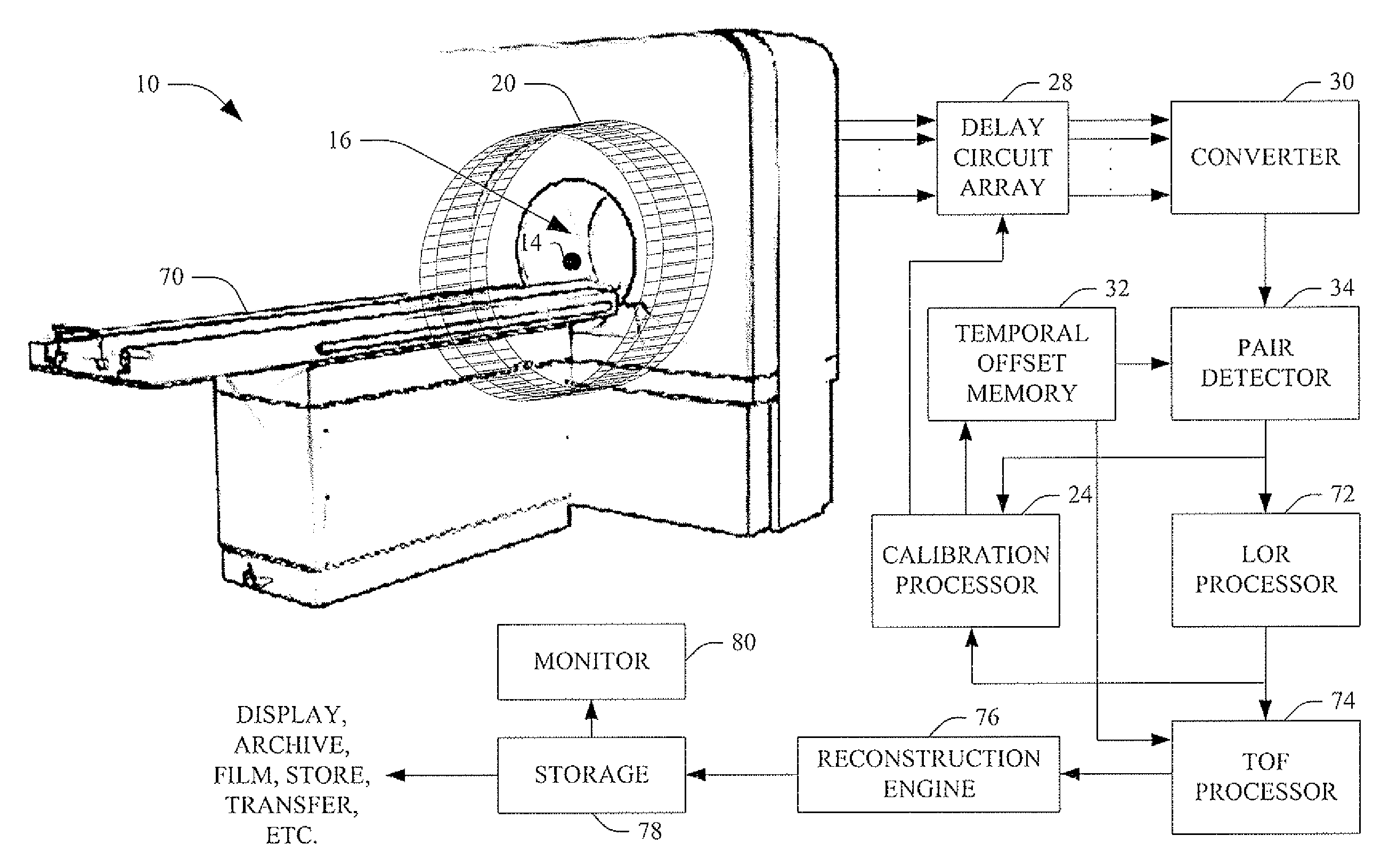
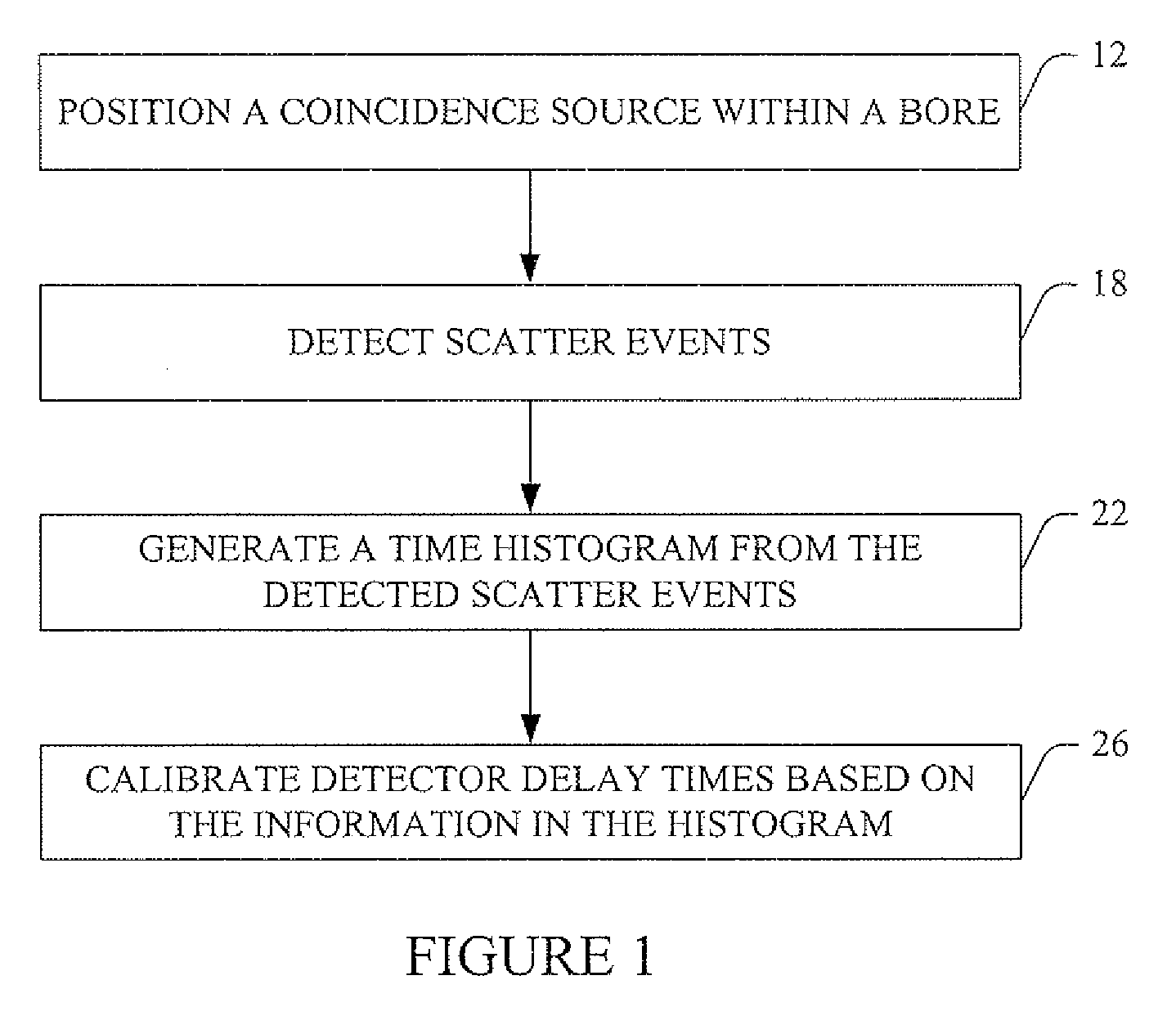
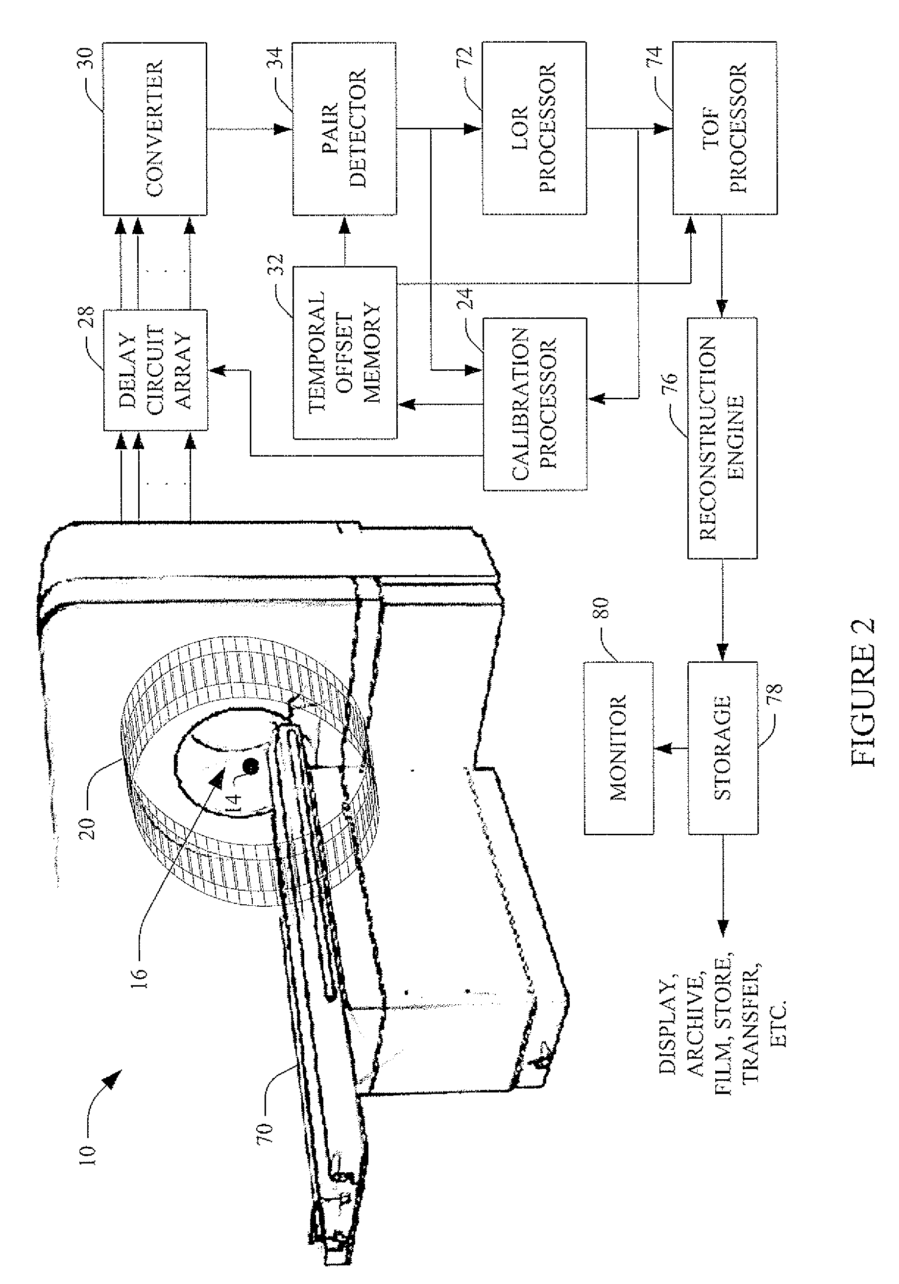
[0020]FIG. 1 illustrates a method for calibrating an imaging system 10 such as illustrated in FIG. 2. The calibration technique calibrates the coincidence timing utilized in time-of-flight (TOF) measurements such as those associated with Positron Emission Tomography (PET).

[0021] At reference numeral 12, a coincidence source 14 is placed within an imaging region 16 (or bore) of a PET scanner 10. The coincidence source can be a point source such as a scatter cylinder (e.g., plastic, steel, etc.), a scatter button (e.g., a 2.5 cm diameter plastic volume of Na-22), etc., or a line source. The coincidence source can be fixed at a position or mobile relative to the bore. In one instance, the coincidence source is fixed at about a center location of the bore. In another instance, the coincidence source is fixed at a known offset from the center of the bore. At 18, coincidence scatter radiation events are detected by detectors of a detector array 20. Such events are coincident events that ...


PUM


Abstract

A method for calibrating an imaging system includes coincident detecting scatter radiation events from a calibration source located within a bore of the imaging system. The scatter radiation events are subsequently used to compute calibration time offsets for each detector channel in the imaging system. Each detector channel is then calibrated with respective calibration time adjustments.

Description

CROSS REFERENCE TO RELATED APPLICATIONS [0001] This application claims the benefit of U.S. provisional application Ser. No. 60 / 755,919 filed Jan. 3, 2006, which is incorporated herein by reference.BACKGROUND [0002] The following relates to medical imaging systems. It finds particular application to calibrating such systems. More particularly, it is directed towards calibrating the coincidence timing utilized in time-of-flight (TOF) measurements, such as those associated with Positron Emission Tomography (PET). [0003] A conventional PET scanner has a plurality of radiation detector modules. The modules are arranged to facilitate positioning a subject such that the modules surround the subject. A radiopharmaceutical is administered to and / or ingested by the subject. The radiopharmaceutical produces radiation decay events in the subject that emit positrons. The positrons travel a relatively short distance before interacting with an electron in an electron-positron annihilation event th...

Claims


Application Information

Patent Timeline
Patent Type & Authority Applications(United States)
IPC IPC(8): G01T1/164
CPCA61B6/037G01T1/2985
Inventor GRIESMER, JEROME J.LAURENCE, THOMAS L.
Owner KONINKLIJKE PHILIPS ELECTRONICS NV
Why Eureka
Try Eureka