Plasma display panel

a technology of plasma and display panel, which is applied in the manufacture of electric discharge tubes/lamps, gas-filled discharge tubes, gas mixture absorption, etc., can solve the problems of reducing the lifetime and characteristics of phosphor materials, and degradation of phosphor materials, so as to prevent contamination of discharge spaces and increase the discharge efficiency of pdp

Inactive Publication Date: 2007-07-05
SAMSUNG SDI CO LTD
View PDF2 Cites 8 Cited by
  • Summary
  • Abstract
  • Description
  • Claims
  • Application Information

AI Technical Summary

Benefits of technology

[0024]According to the present embodiments, contamination of a discharge space can be prevented and discharge efficiency of the PDP can be increased by coating a material on barrier ribs to adsorb contamination materials such as residual carbon or moisture generated from phosphor layers.

Problems solved by technology

However, residual carbon that has not completely burnt or other organic materials cause outgassing.
A discharge gas in discharge cells is contaminated by these gases, thereby reducing the lifetime and characteristics of the phosphor material.
The moisture in the discharge cell can cause degradation of the phosphor material.

Method used


Image

  • Plasma display panel
  • Plasma display panel
  • Plasma display panel

Examples


Embodiment Construction

[0029]The present embodiments will now be described more fully with reference to the accompanying drawings in which exemplary embodiments are shown.

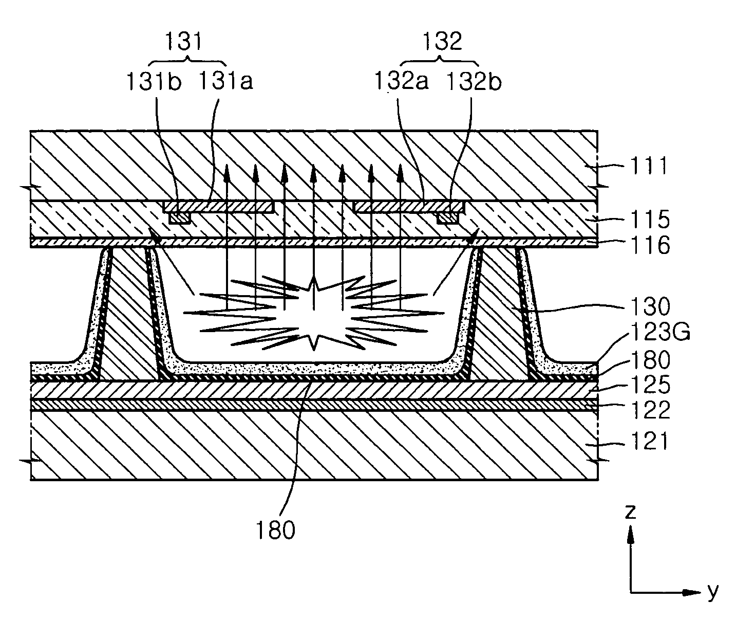
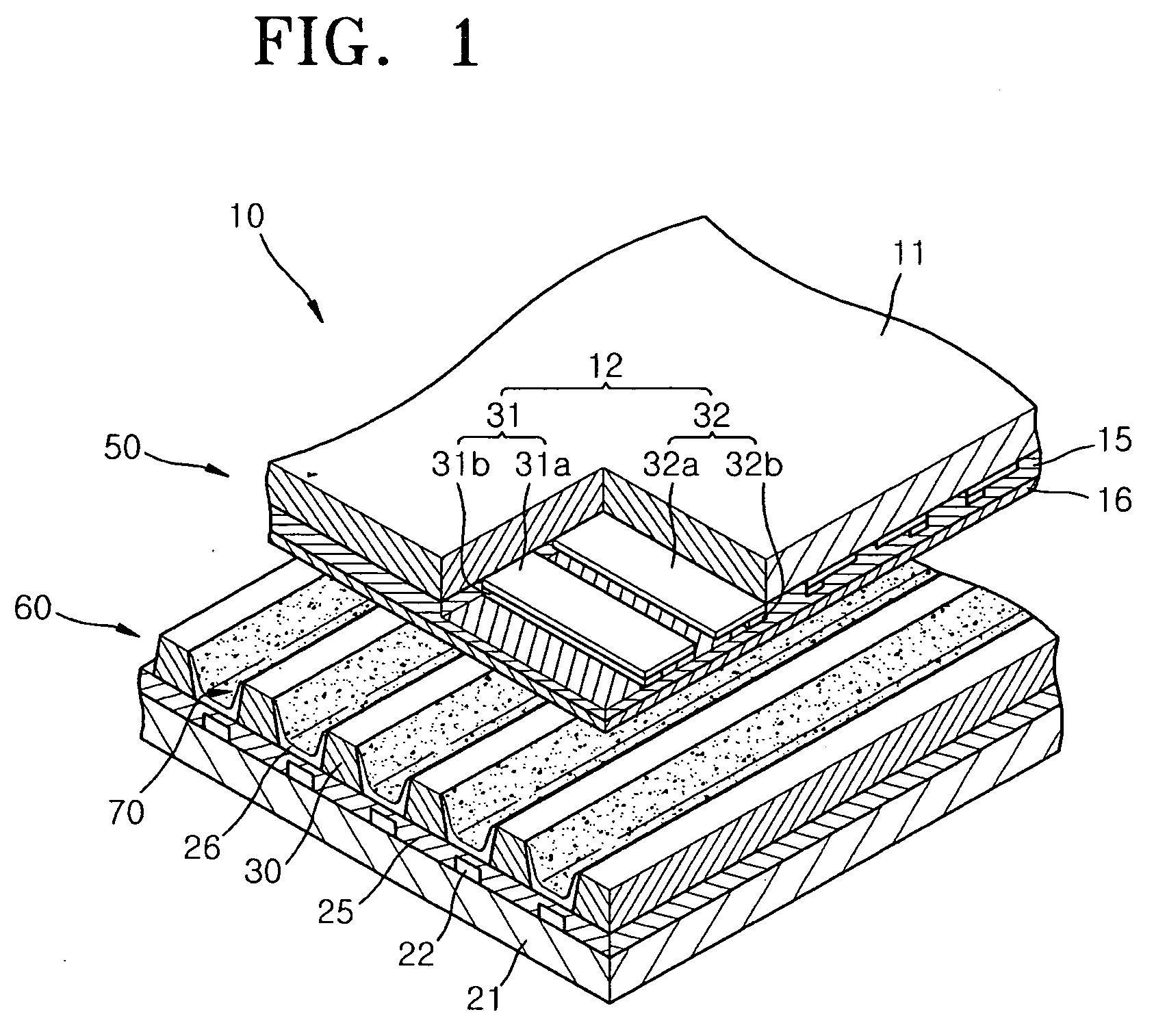
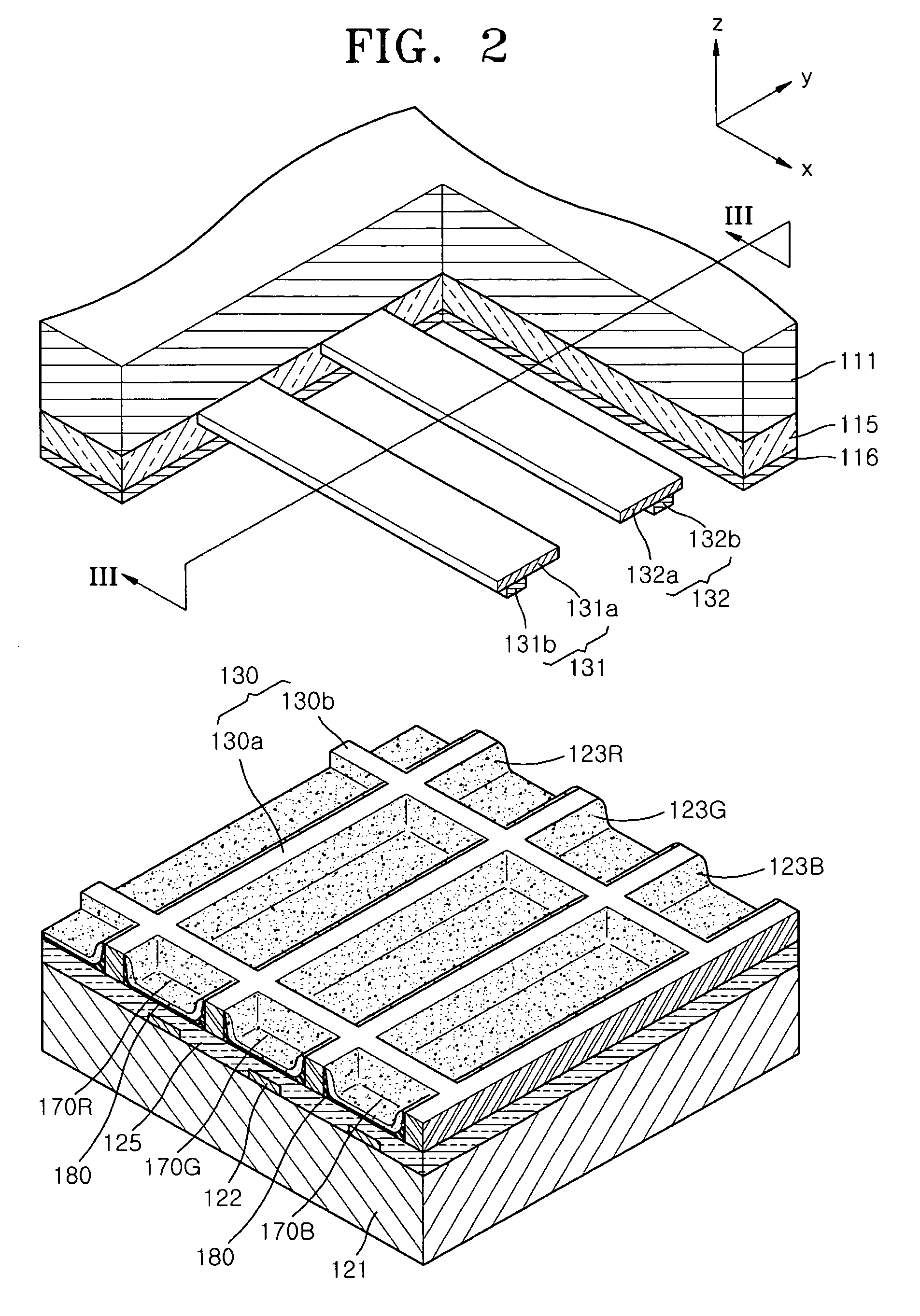
[0030]FIG. 2 is a partial cutaway exploded perspective view illustrating a plasma display panel (PDP) according to an embodiment, and FIG. 3 is a cross-sectional view taken along line III-III of FIG. 2.

[0031]Referring to FIGS. 2 and 3, an AC PDP is depicted in FIG. 2. The PDP includes a first substrate 111, a second substrate 121, sustain electrode pairs 131 and 132, address electrodes 122, a plurality of barrier ribs 130, a protective layer 116, phosphor layers 123R, 123G, and 123B, a first dielectric layer 115, a second dielectric layer 125, a discharge gas (not shown), and an adsorption layer 180.

[0032]The first substrate 111 can be a front substrate, and the second substrate 121 can be a rear substrate. The first dielectric layer 115 can be a front dielectric layer, and the second dielectric layer 125 can be a rear dielectric layer.

[...


PUM


Abstract

Provided is a plasma display panel that displays images using visible light emitted from phosphor layers formed in discharge cells as a result of discharges in the discharge cells. The plasma display panel includes a first substrate and a second substrate facing each other, a plurality of barrier ribs disposed to define a space into a plurality of discharge cells between the first and second substrates, sustain electrode pairs extending in a direction on the first substrate crossing the discharge cells, address electrodes crossing the sustain electrode pairs, a first dielectric layer covering the sustain electrode pairs, a second dielectric layer covering the address electrodes, phosphor layers formed in the discharge cells, and an adsorption layer formed in the discharge cells to adsorb impurity gasses and moisture in the discharge cells.

Description

CROSS-REFERENCE TO RELATED APPLICATIONS[0001]This application claims the benefit of Korean Patent Application No. 10-2005-0135865, filed on Dec. 30, 2005, in the Korean Intellectual Property Office, the disclosure of which is incorporated herein in its entirety by reference.BACKGROUND OF THE INVENTION[0002]1. Field of the Invention[0003]The present embodiments relate to a plasma display panel, and more particularly, to a plasma display panel that displays an image made by combining visible light, which is emitted from a phosphor material of a phosphor layer formed in a discharge cell due to discharges in the discharge cell.[0004]2. Description of the Related Art[0005]Plasma display panels, which are expected to replace conventional cathode ray tube display devices, have received much attention. Plasma display panels display images using visible light emitted through a process in which a phosphor material formed in a predetermined pattern in a space is excited with ultraviolet rays g...

Claims


Application Information

Patent Timeline
Patent Type & Authority Applications(United States)
IPC IPC(8): H01K1/00H01J17/49
CPCH01J11/52H01J11/12H01J11/36H01J11/40H01J2209/3855
Inventor YOO, YOUNG-GIL
Owner SAMSUNG SDI CO LTD
Why Eureka
Try Eureka