Plasma display panel and method for producing the same

a technology of plasma display panel and display panel, which is applied in the manufacture of electrode systems, electrical discharge tubes/lamps, and electrodes, etc., can solve the problems of short circuit of electrodes and the failure of the protective layer of magnesium oxide to sufficiently lower the discharge voltage of plasma display panels, so as to improve the secondary electron emission characteristics and

Inactive Publication Date: 2007-07-05
LG ELECTRONICS INC
View PDF1 Cites 28 Cited by
  • Summary
  • Abstract
  • Description
  • Claims
  • Application Information

AI Technical Summary

Benefits of technology

[0010] In one general aspect, a plasma display panel that has improved secondary electron emission characteristics and a method for producing such a plasma display panel are provided.
[0011] Implementations of the plasma display panel may have low firing voltage, high brightness, improved discharge efficiency and reduced power consumption, which result from improved secondary electron emission characteristics.

Problems solved by technology

Thus, short circuiting of the electrodes may be caused by metal elements, such as sodium (Na).
However, such a conventional protective layer of magnesium oxide may fail to sufficiently lower the discharge voltage of plasma display panels, on account of its material characteristics.

Method used


Image

  • Plasma display panel and method for producing the same
  • Plasma display panel and method for producing the same
  • Plasma display panel and method for producing the same

Examples


Embodiment Construction

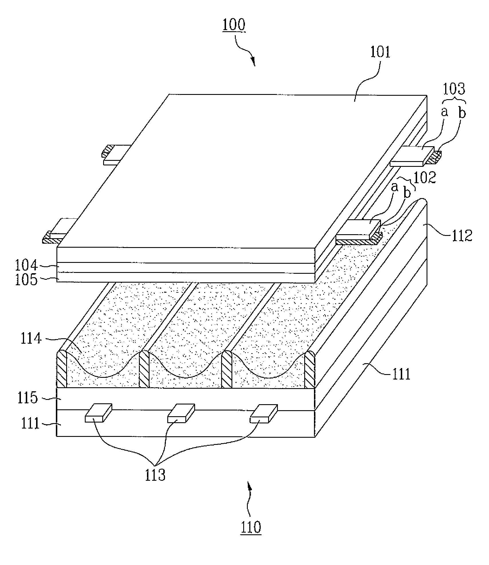
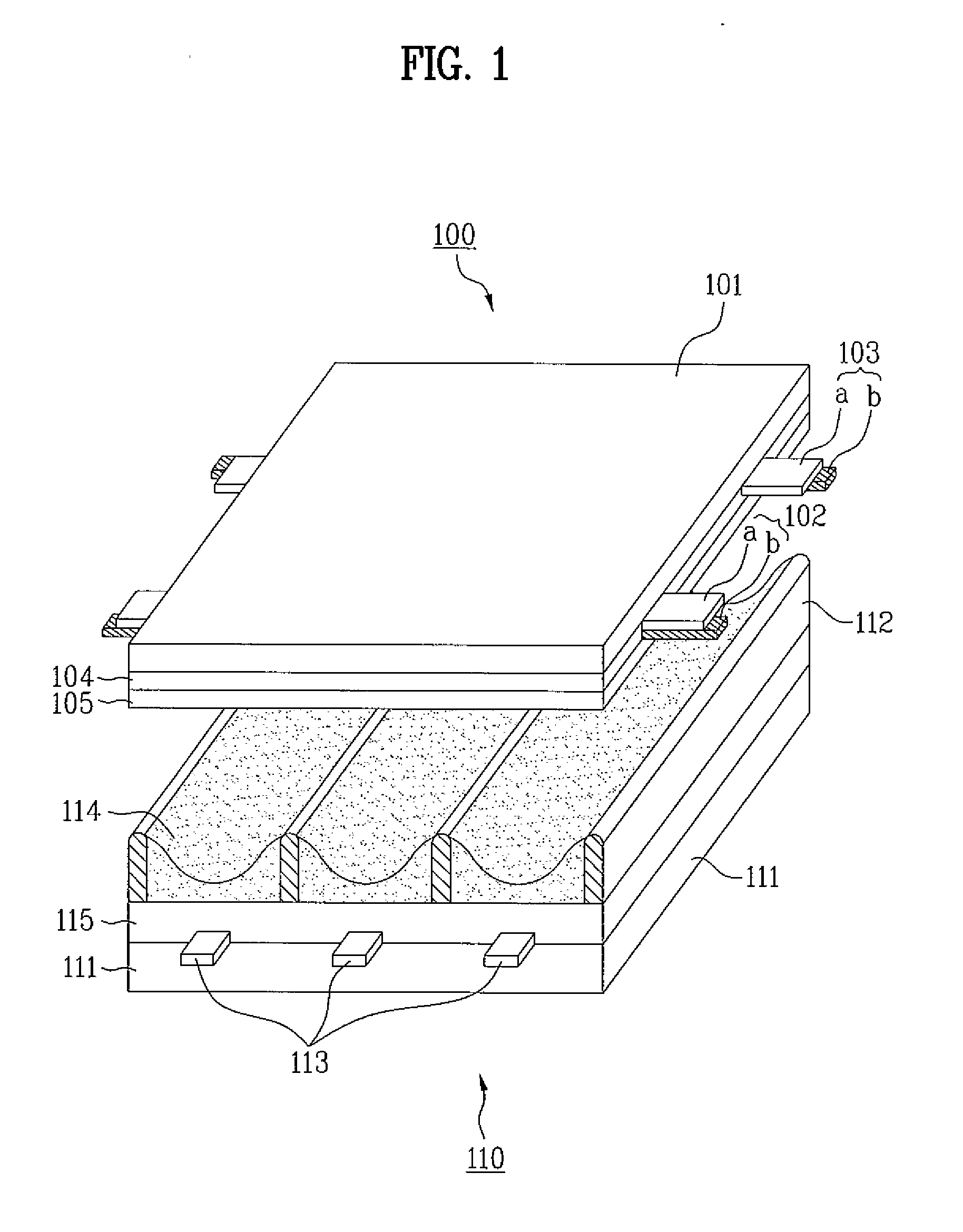
[0020] A plasma display panel includes a protective layer having a bilayer structure. Hereinafter, a layer formed on one surface of an upper dielectric layer is referred to as a ‘first protective film’, and a layer formed on the first protective film is referred to as a ‘second protective film’.

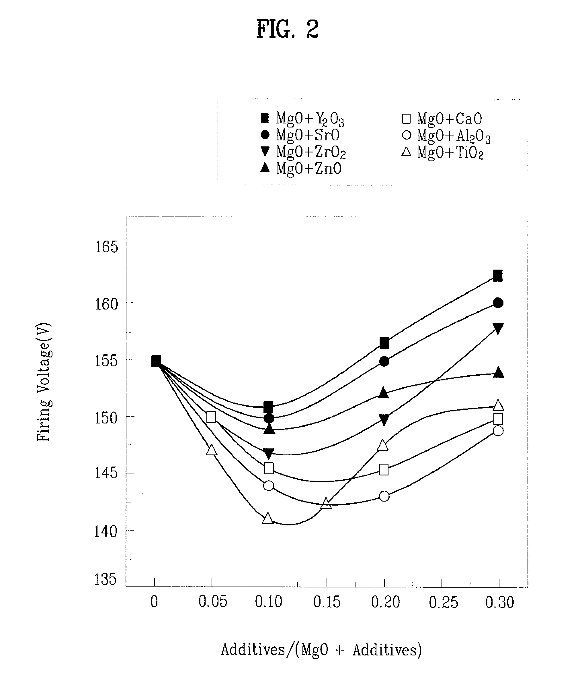
[0021]FIG. 2 is a graph showing changes in the firing voltages of different plasma display panels, each of which includes a protective layer composed of magnesium oxide and another oxide. As is apparent from the graph of FIG. 2, the firing voltages of the plasma display panels can be lowered by the addition of various kinds of oxides other than magnesium oxide to the respective protective layers. FIG. 2 also shows changes in the firing voltages of the plasma display panels with increasing amounts of Y2O3, SrO, ZrO2, ZnO, CaO, Al2O3 and TiO2 added as additives. Although there is a difference depending on the kind of the additives, the firing voltages of the plasma display panels generally dec...


PUM


Abstract

A plasma display panel with low firing voltage is disclosed. The plasma display panel includes an upper panel and a lower panel facing each other through barrier ribs wherein the upper panel includes a first protective film composed of magnesium oxide and a second protective film formed on the first protective film and composed of a secondary electron-emitting material.

Description

[0001] This application claims the benefit of Korean Patent Application No. 10-2006-0000849, filed on Jan. 4, 2006 and Korean Patent Application No. 10-2006-0001884, filed on Jan. 6, 2006, which are hereby incorporated by reference in their entirety. BACKGROUND [0002] 1. Technical Field [0003] This document relates to a plasma display panel, and more particularly, to protective films of a plasma display panel. [0004] 2. Discussion of the Related Art [0005] Plasma display panels include an upper panel, a lower panel, and barrier ribs formed between the upper and lower panels to define respective discharge cells. A major discharge gas, such as neon, helium or a mixed gas thereof, and an inert gas containing a small amount of xenon (Xe) are filled within the discharge cells. When a high-frequency voltage is applied to produce discharge in the discharge cells, vacuum ultraviolet rays are generated from the inert gas to cause phosphors present between the barrier ribs to emit light, and,...

Claims


Application Information

Patent Timeline
Patent Type & Authority Applications(United States)
IPC IPC(8): H01J17/49H01J9/02H01J11/12H01J11/22H01J11/24H01J11/26H01J11/34H01J11/36H01J11/38H01J11/40H01J11/42H01J11/44H01J11/50
CPCH01J9/02H01J11/40H01J11/12
Inventor KIM, BO HYUNPARK, MIN SOOPARK, DEOK HAIRYU, BYUNG GILKIM, YOUNG SUNG
Owner LG ELECTRONICS INC
Why Eureka
Try Eureka