Method and apparatus for modifying the spread of a laser beam

a laser beam and laser beam technology, applied in the direction of lasers, semiconductor laser optical devices, underwater structures, etc., can solve the problems of potentially hazardous products containing laser devices for the eye, and the performance of speckle-based motion sensors may not be at an acceptable level

Inactive Publication Date: 2007-07-05
AVAGO TECH WIRELESS IP SINGAPORE PTE
View PDF32 Cites 83 Cited by
  • Summary
  • Abstract
  • Description
  • Claims
  • Application Information

AI Technical Summary

Problems solved by technology

Therefore, if a person looks into the laser beam, it may damage to the unaided eye eye and even if the laser beam is not powerful enough to cause damage, one may further focus the laser beam with a magnifying lens or other apparatus such that the further focused beam is capable of causing damage to the eye.
Because products containing laser devices are potentially hazardous to the eye, they are classified accordingly by their potential hazard level.
This class consists of lasers that are safe under reasonably foreseeable conditions of operation, but may be hazardous if the user employs an optical device for intra-beam viewing, i.e. a magnifying lens.
That is, if the power is reduced to the Class 1 requirements, the speckle-based motion sensor may not perform at an acceptable level.

Method used


Image

  • Method and apparatus for modifying the spread of a laser beam
  • Method and apparatus for modifying the spread of a laser beam
  • Method and apparatus for modifying the spread of a laser beam

Examples


Embodiment Construction

[0018] The following discussion is presented to enable a person skilled in the art to make and use the invention. The general principles described herein may be applied to embodiments and applications other than those detailed below without departing from the spirit and scope of the present invention. The present invention is not intended to be limited to the embodiments shown, but is to be accorded the widest scope consistent with the principles and features disclosed or suggested herein.

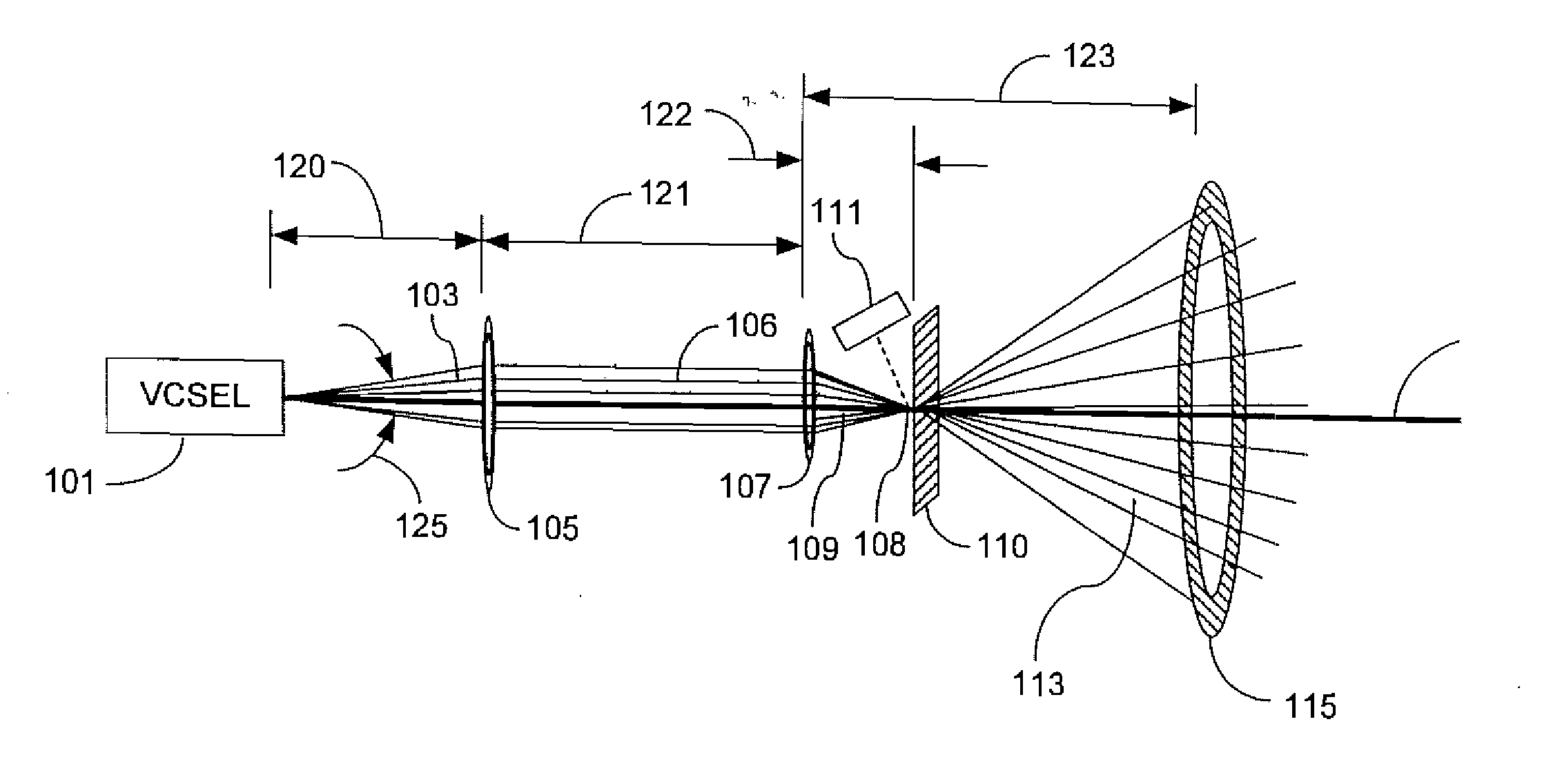
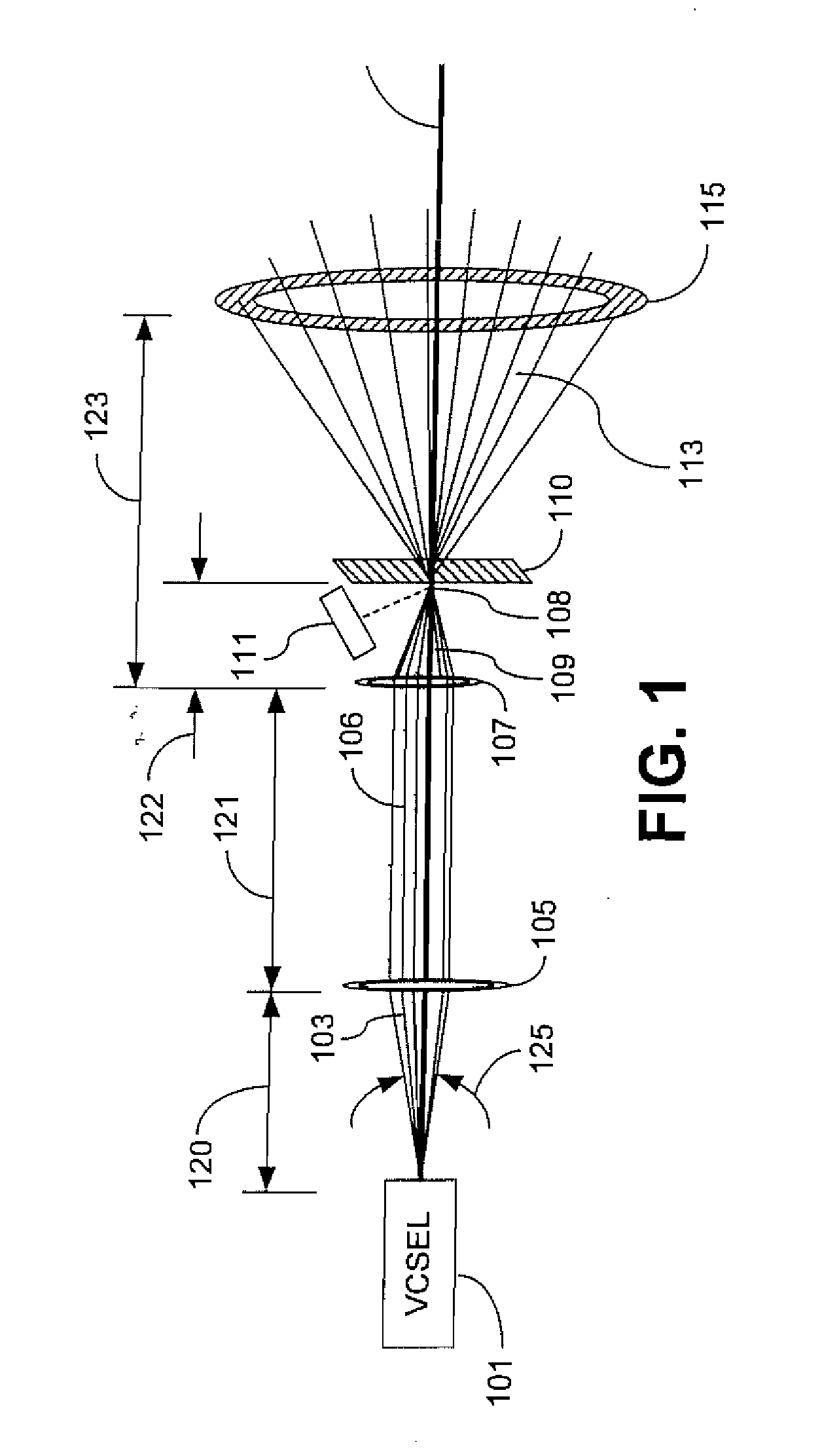
[0019]FIG. 1 is a diagram of an apparatus for modifying a laser beam for use in an optical mouse according an embodiment of the invention. In this embodiment, a Vertical Cavity Surface Emitting Laser (VCSEL) 101 emits an 850 nm wavelength laser beam along an optical axis 102. A typical VCSEL 101 will have an associated divergence angle 125 which is a measure of the widest angle at which individual rays of the laser beam emanate from the VCSEL 101. Typically, the divergence angle 125 is defined as ...


PUM


Abstract

An apparatus and method for modifying the spread of a laser beam. The apparatus comprises a laser source operable to generate a laser beam having a flux that exceeds a predetermined value and an optical train operable to modify the beam such that the flux of the beam through a predetermined aperture does not exceed the predetermined value. The optical train may include a focusing lens, a diffractive focusing vortex lens, a beam splitting device, or a two-dimensional diffraction grating.

Description

[0001] This is a divisional of co-pending application Ser. No. 10 / 366,755 filed on Feb. 13, 2003, the entire disclosure of which is incorporated into this application by reference.BACKGROUND OF THE INVENTION [0002] Many of today's devices use lasers to implement various functions. For example, an optical mouse or laser pointer use lasers in their respective operations. Additionally, many fiber-optic communication devices use a laser as a source of signal generation. [0003] These lasers generate optical beams that can sometimes generate light powerful enough to damage the human eye. For example, a laser-optic pointing device typically includes a beam-altering apparatus in optical alignment with the laser designed to focus or collimate the laser beam for its intended use. Therefore, if a person looks into the laser beam, it may damage to the unaided eye eye and even if the laser beam is not powerful enough to cause damage, one may further focus the laser beam with a magnifying lens or...

Claims


Application Information

Patent Timeline
Patent Type & Authority Applications(United States)
IPC IPC(8): G01B11/02G02B27/00G02B27/09G02B27/20G02B27/10G06F3/03H01S3/00H01S3/13H01S5/00H01S5/06H01S5/183
CPCG06F3/0317H01S5/183H01S5/005H01S3/10H01S5/06E02D29/0266E02B3/14E02D2600/20
Inventor GRUHLKE, RUSSELL W.TRUTNA, WILLIAM RICHARD JR.
Owner AVAGO TECH WIRELESS IP SINGAPORE PTE
Why Eureka
Try Eureka