Fuel cell system

a fuel cell and system technology, applied in the field of fuel cell systems, can solve the problems of sometimes deteriorating power generation efficiency in the entire fuel cell stack, and achieve the effects of preventing flooding in the anode, reducing the amount of hydrogen purge for discharging impurities, and improving the efficiency of fuel gas us

Inactive Publication Date: 2007-07-05
TOYOTA JIDOSHA KK
View PDF5 Cites 8 Cited by
  • Summary
  • Abstract
  • Description
  • Claims
  • Application Information

AI Technical Summary

Benefits of technology

[0011] In the above-mentioned fuel cell system, when the opening and closing unit provided on the exhaust passage is closed, the flow amount controlling unit executes the control such that the flow amount ratios of the first and second supply passages vary in terms of time. Thereby, an extreme downstream position of the fuel gas can be varied. The “extreme downstream position” is the position where the fuel gas supplied via the first and the second supply passages meet with each other and consumed for the cell reaction, and as a result the flow rate of the fuel gas becomes zero. The extreme downstream position can be moved in the anode we well as in the first and the second supply passages by controlling the flow amounts of the fuel gas. Therefore, the impurities such as the nitrogen can be diffused within the anode. Thus, hydrogen purge amount for discharging the impurities can be reduced, and the efficiency of using the fuel gas can be improved. Additionally, by varying the extreme downstream position of the fuel gas, not only the diffusion of the impurities but also the diffusion of dew water can be carried out. Thereby, flooding in the anode can be prevented. Further, since it becomes possible to efficiently use the dew water as humidification water in the fuel cell stack, dryout of the fuel cell stack can be prevented.
[0012] The flow amount controlling unit may control the flow amount such that an extreme downstream position of the fuel gas coincides with a position at which the exhaust passage is connected to the second supply passage, when the opening and closing unit is open. When the opening and closing unit provided on the exhaust passage is open, the impurities in the anode is discharged with unused hydrogen. In the above-mentioned fuel cell system, at the time of discharging the impurities, the flow amount is controlled so that the extreme downstream position of the hydrogen coincides with the position at which the exhaust passage is arranged. Thereby, the impurities can be effectively exhausted.
[0013] In a preferred embodiment, the flow amount controlling unit may control the flow amounts such that the flow amounts of the fuel gas intermittently vary. For example, the valve supplying the hydrogen is intermittently controlled. Further, the flow amount controlling unit may shift a time period in which the fuel gas is supplied to the anode through the first supply passage from a time period in which the fuel gas is supplied to the anode through the second supply passage. Thereby, the pulsation can be introduced to the flow of the fuel gas in the anode, and the extreme downstream position in the anode can be finely and quickly moved. Therefore, the impurities can be effectively diffused.
[0014] In another preferred embodiment, the fuel cell system may further include an flow amount calculating unit which calculates a required flow amount of the fuel gas to be supplied to the fuel cell stack based on a state of the fuel cell stack, and the flow amount controlling unit may control the flow amounts of the fuel gas such that a total of the flow amounts of the fuel gas supplied from the first and the second supply passages to the anode corresponds to the required flow amount calculated by the flow amount calculating unit. Thereby, the hydrogen of the necessary flow amount can be supplied to the fuel cell stack, and the necessary power generation amount can be maintained.
[0015] In an embodiment, the exhaust passage may be connected to the second supply passage at the position between the fuel stack and the opening and closing unit. Thereby, the extreme downstream position of the hydrogen can be moved within a large range in the almost entire fuel cell stack. Therefore, the impurities in the anode can also be diffused within the large range, and the hydrogen purge amount can be further reduced. Moreover, since a power generation distribution of an inside surface of the anode can be further equalized, durability of the fuel cell stack can also be improved. It is preferable that a volume of the second supply passage between the anode and the exhaust passage is small. Thereby, without increasing the discharging amount of unused hydrogen, the impurities can be efficiently discharged.
[0016] According to another aspect of the present invention, there is provided a method of supplying fuel gas to a fuel cell system including a fuel cell stack having an anode and a cathode; a first and a second supply passages which communicate with each other in the fuel cell stack and supply fuel gas to the anode, respectively; and an exhaust passage which is connected to the second supply passage and discharges exhaust gas from the anode, the method including the steps of: a step of opening and closing the exhaust passage; and a step of controlling flow amounts of the fuel gas passing through the first supply passage and the second supply passage, respectively, wherein the step of controlling flow amounts varies a ratio between the flow amounts passing through the first supply passage and the second supply passage, when the exhaust passage is closed. By executing the above method, hydrogen purge amount for discharging the impurities can be reduced, and the efficiency of using the fuel gas can be improved.

Problems solved by technology

However, in the above-mentioned fuel cell systems, since the impurities accumulate at one portion in the fuel cell stack, the power generation efficiency in the entire fuel cell stack sometimes deteriorates.

Method used


Image

  • Fuel cell system
  • Fuel cell system
  • Fuel cell system

Examples


Embodiment Construction

[0027] The preferred embodiments of the present invention will now be described below with reference to the attached drawings.

[Configuration of Fuel Cell System]

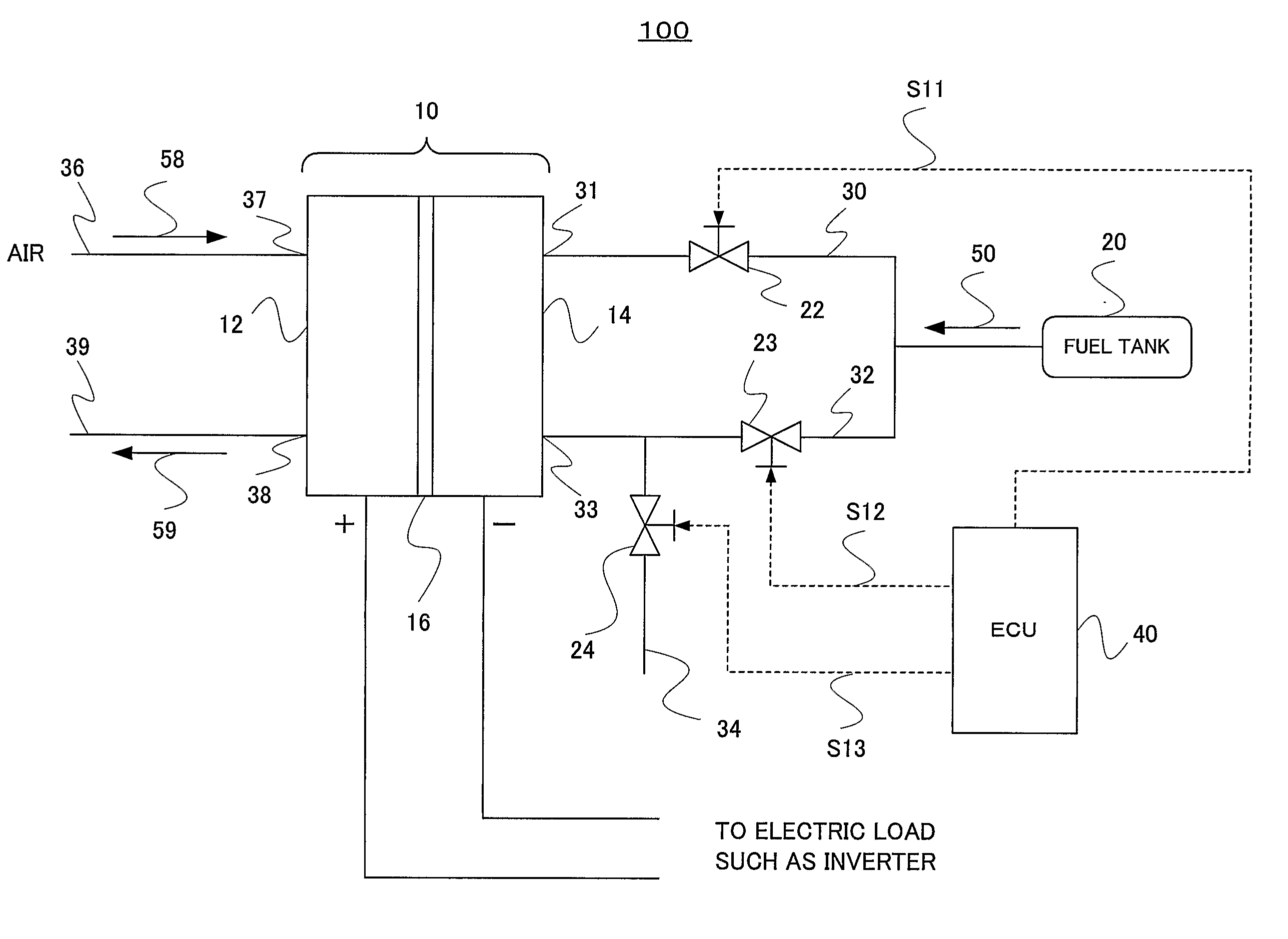
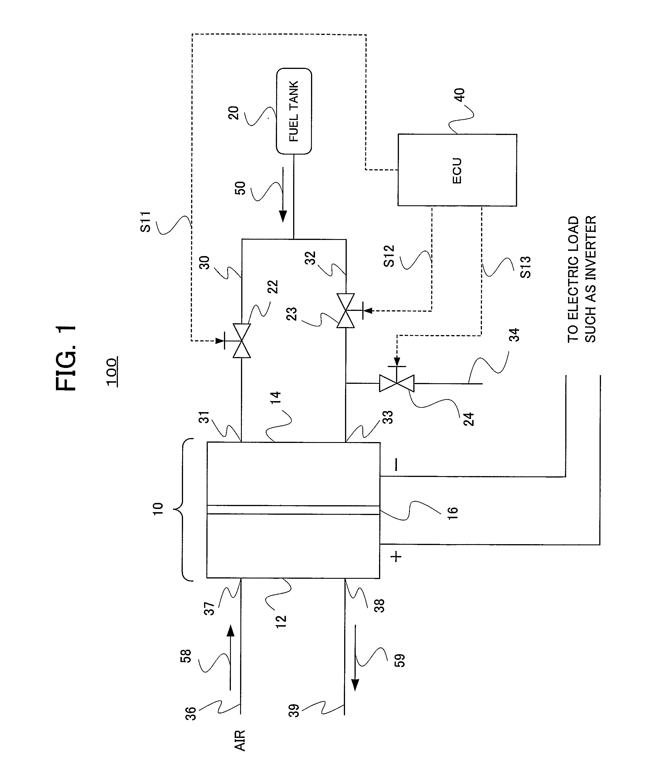
[0028]FIG. 1 is a diagram schematically showing a configuration of a fuel cell system according to an embodiment of the present invention.

[0029] In FIG. 1, a fuel cell system 100 mainly includes a fuel cell stack 10, a fuel tank 20, an ECU (Engine Control Unit) 40, valves 22 to 24, hydrogen supply passages 30 and 32, hydrogen supply openings 31 and 33, a hydrogen exhaust passage 34, an air supply passage 36, an air supply opening 37, an air exhaust opening 38 and an air exhaust passage 39. The fuel cell system 100 is loaded on a fuel cell automobile (hereinafter, simply referred to as “vehicle”).

[0030] The fuel cell stack 10 is manufactured by stacking cells with conductive separators sandwiched between the cells. The cell has an electrolyte membrane 16, and electrodes having a configuration of a porous layer capable of ...


PUM

PropertyMeasurementUnit
voltageaaaaaaaaaa
timeaaaaaaaaaa
electric poweraaaaaaaaaa

Abstract

A fuel cell system (100) includes two supply passages (30, 32) for supplying the hydrogen to the anode (14). Valves (22, 23) which control flow amounts of the hydrogen passing through the two supply passages (30, 32) are provided. An exhaust passage (34) which outputs exhaust gas from the anode (14) is provided on the supply passage, and a valve (24) is also provided. When the valve (24) on the exhaust passage (34) is closed, the flow amount ratios of the hydrogen passing through the two supply passages (30, 32) are varied in time. Therefore, impurities such as nitrogen can be diffused. Thereby, a hydrogen purge amount can be reduced.

Description

BACKGROUND OF THE INVENTION [0001] 1. Field of the Invention [0002] This invention relates to a fuel cell system, and more particularly to an improvement of efficiency in using a full gas. [0003] 2. Description of Related Art [0004] There is known a fuel cell system loaded on a fuel cell automobile and the like. The fuel cell system has a fuel cell stack, as a main body, which is constructed by an anode (i.e., a hydrogen electrode or a fuel electrode) and a cathode (i.e., an oxygen electrode). The fuel cell system also has a tank which stores fuel gas such as hydrogen supplied to the anode, a pump which returns exhaust gas including unused fuel gas to the original anode and the like. In the fuel cell stack, the hydrogen and the oxygen included in the air react on each other to generate an electric power. [0005] In the fuel cell system, as a cell reaction proceeds, nitrogen in oxidized gas as well as water and moisture for humidification pass through an electrolyte membrane from the ...

Claims


Application Information

Patent Timeline
Patent Type & Authority Applications(United States)
IPC IPC(8): H01M8/04
CPCH01M8/04089H01M8/04104Y02E60/50H01M8/04231H01M8/04753H01M8/04126
Inventor KATANO, KOJI
Owner TOYOTA JIDOSHA KK
Why Eureka
Try Eureka