Felt for forming fiber cement articles having stretch-resistant yarns

a fiber cement and yarn technology, applied in the field of fiber cement, can solve the problems of fiber cement felts being prone to blinding, fiber cement felts are typically exposed to high load conditions, and felts are prone to significant “compaction, so as to improve stretch resistance and tenacity

Inactive Publication Date: 2007-07-05
WEAVEXX
View PDF6 Cites 13 Cited by
  • Summary
  • Abstract
  • Description
  • Claims
  • Application Information

AI Technical Summary

Benefits of technology

[0008] As a first aspect, embodiments of the present invention are directed to a felt for making fiber cement slates or tubes. The fiber cement felt comprises: a base fabric including a set of machine direction (MD) yarns and a set of cross machine direction (CMD) yarns interwoven with the MD yarns in a plurality of repeat units, wherein between about 5 and 95 percent of the MD yarns are stretch-resistant yarns; and a batt layer overlying and attached to the fabric. A fiber cement felt of this configuration can exhibit improved stretch-resistance and tenacity.

Problems solved by technology

For example, fiber cement felts are typically exposed to high load conditions by the forming machine.
However, because the yarns are coarse, such felts have a tendency to mark the surface of the fiber cement product formed thereon, sometimes to a sufficient degree that smoothing of the surface in a subsequent operation may be required.
Further, fiber cement felts are typically prone to “blinding” (the filling of the openings in the fabric mesh with fiber cement slurry) and typically must be cleaned frequently and may be removed (depending on machine conditions such as speed and load) after as little as one week.
Also, such felts tend to suffer significant “compaction” (the tendency of the felt to decrease in thickness) with use.
Compaction is detrimental to operation in that, as the felt decreases in thickness, the pressure exerted on the fiber cement by the pressing rolls can change, thereby altering the surface characteristics as well as overall physical properties of the sheet.
However, it has been noted that fiber cement felts tend to be susceptible to stretching, particularly in the machine direction, during operation.

Method used


Image

  • Felt for forming fiber cement articles having stretch-resistant yarns
  • Felt for forming fiber cement articles having stretch-resistant yarns
  • Felt for forming fiber cement articles having stretch-resistant yarns

Examples


Embodiment Construction

[0015] The present invention will now be described more fully hereinafter, in which embodiments of the invention are shown. This invention may, however, be embodied in different forms and should not be construed as limited to the embodiments set forth herein. Rather, these embodiments are provided so that this disclosure will be thorough and complete, and will fully convey the scope of the invention to those skilled in the art. In the drawings, like numbers refer to like elements throughout. Thicknesses and dimensions of some components may be exaggerated for clarity.

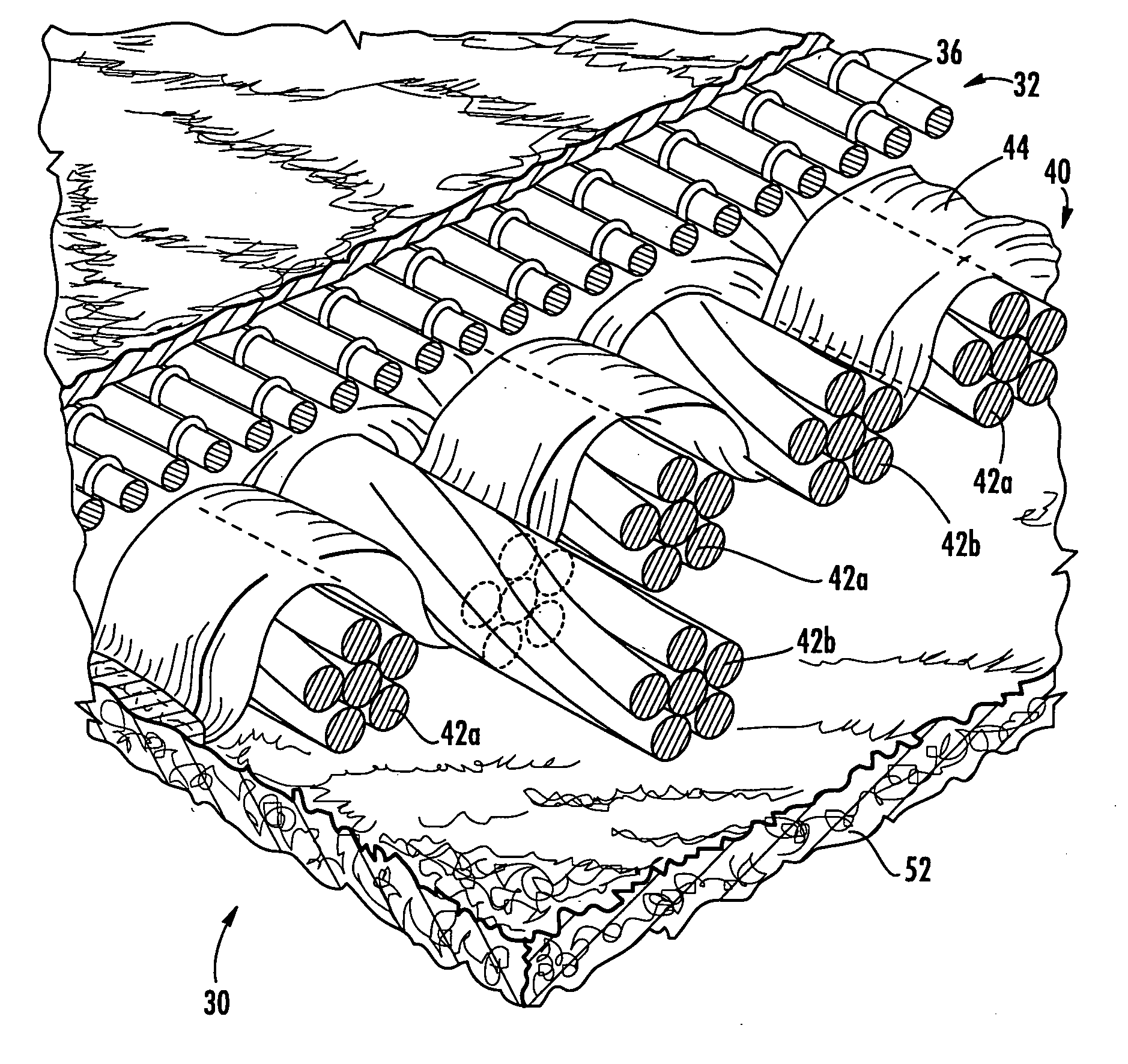
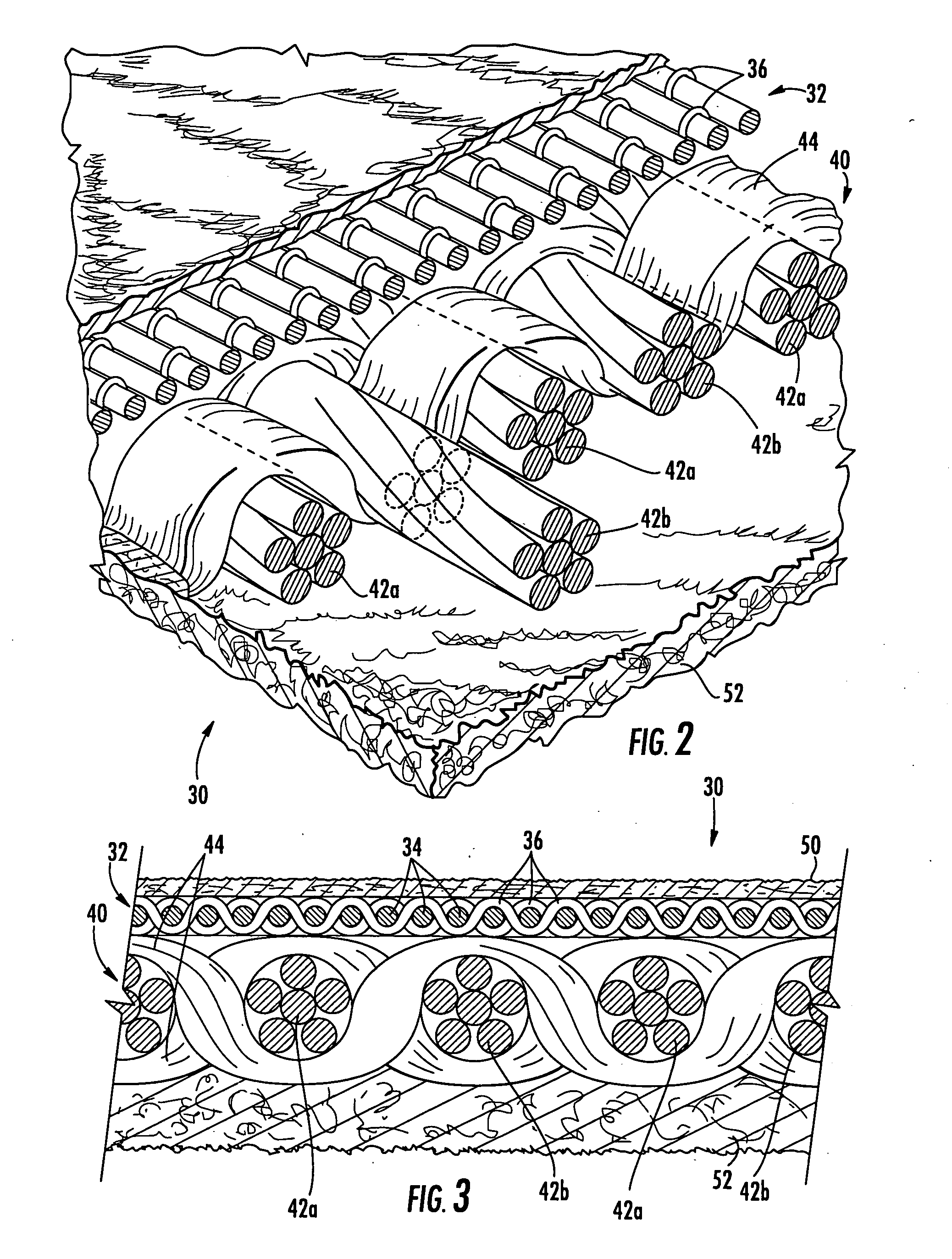
[0016] As used herein, the terms “machine direction” (MD) and “cross machine direction” (CMD) refer, respectively, to a direction aligned with the direction of travel of the fiber cement felt on a fiber cement forming machine, and a direction parallel to the fabric surface and transverse to the direction of travel. Also, both the flat weaving and endless weaving methods described hereinabove are well known in this art,...


PUM

PropertyMeasurementUnit
breaking elongationaaaaaaaaaa
thicknessaaaaaaaaaa

Abstract

A fiber cement felt includes: a base fabric including a set of machine direction (MD) yarns and a set of cross machine direction (CMD) yarns interwoven with the MD yarns in a plurality of repeat units, wherein between about 5 and 95 percent of the MD yarns are stretch-resistant yarns; and a batt layer overlying and attached to the fabric. A fiber cement felt of this configuration can exhibit improved stretch-resistance and tenacity.

Description

FIELD OF THE INVENTION [0001] The present invention relates generally to fabrics, and more particularly to fabrics employed to form articles of fiber cement. BACKGROUND OF THE INVENTION [0002] Fiber cement is a well-known material employed in many building components, such as siding, roofing and interior structures, and pipes, particularly for waste water transport. Fiber cement typically comprises a mixture of cement (i.e., lime, silica and alumina), clay, a thickener, inorganic fillers such as calcium carbonate, and one or more fibrous materials. In the past, asbestos was commonly included as the fibrous material (see U.S. Pat. No. 4,216,043 to Gazzard et al.); because of the well-documented problems asbestos presents, now fiber cement typically includes a natural or synthetic fiber, such as acrylic, aramid, polyvinyl alcohol, polypropylene, cellulose or cotton. Fiber cement is popular for the aforementioned applications because of its combination of strength, rigidity, impact res...

Claims


Application Information

Patent Timeline
Patent Type & Authority Applications(United States)
IPC IPC(8): D04H1/08B32B13/02B32B5/16B32B5/26B32B13/10B32B5/02B32B9/02
CPCB28B1/527B32B5/08B32B5/12B32B5/26B32B2419/00B32B13/02B32B2262/0261B32B2262/0269B32B2262/14B32B5/024Y10T442/57Y10T442/50Y10T428/249932Y10T442/56Y10T442/59
Inventor BAUMGARTNER, THOMASGSTREIN, HIPPOLIT
Owner WEAVEXX
Why Eureka
Try Eureka