
Sliding door for motor vehicles and method for the assembly thereof

a technology for sliding doors and motor vehicles, applied in the direction of doors, roofs, wing accessories, etc., can solve the problems of difficult sliding movement, no independent common points, and relatively complex power supply of sliding doors, and achieve the effect of simple and cost-effective power supply and flexible us

Inactive Publication Date: 2007-07-12
BROSE FAHRZEUGTEILE GMBH & CO KG
View PDF17 Cites 11 Cited by
  • Summary
  • Abstract
  • Description
  • Claims
  • Application Information

AI Technical Summary

Benefits of technology

[0008] The object of the present invention is to provide a guide concept such that sliding doors can be assembled in a simple and cost-effective manner to supply power flexibly and customer-specifically.
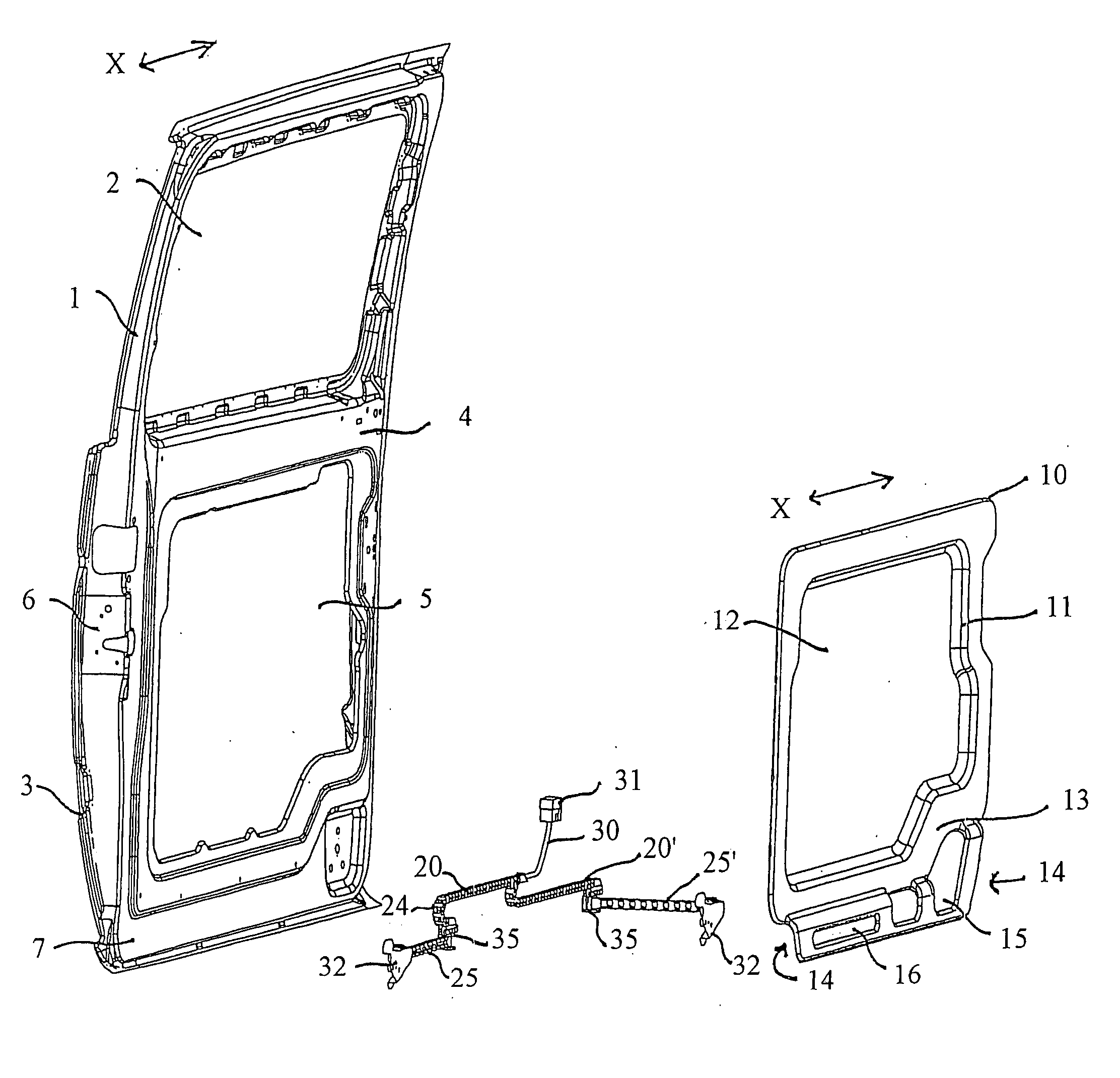
[0010] In a sliding door according to the present invention, guide surfaces of the guide channel are formed or integrated at least in sections on the inner door skin and / or on a door module support capable of being joined to the inner door skin and / or on the door inside trim. It is advantageous to be able to adapt the sliding door easily to the different types of cable guide assemblies. In this regard, the electric cables are accommodated and guided in the cable guide assembly such that the electric cables cannot snag or become entangled when the door is moved. The cable guide assembly for its part is accommodated so as to be movable in an appropriate guide channel which is guided by the cable guide assembly on moving the sliding door to enable compensation of the cable in the sliding plane or in the longitudinal direction of the vehicle and in a direction transverse to the sliding plane.
[0012] It is also possible to reduce the assembly effort required for final installation by integrating the cable guide assembly in the door module support because all the elements required for supplying the door with electricity may be pre-assembled and pre-installed and then connected to the sliding door and inserted into the vehicle. If the guide of the cable guide assembly is formed on the door module support, on a side wall thereof for example, it is possible to save on additional elements for forming such a guide structure which leads to a not inconsiderable weight saving in sliding doors.
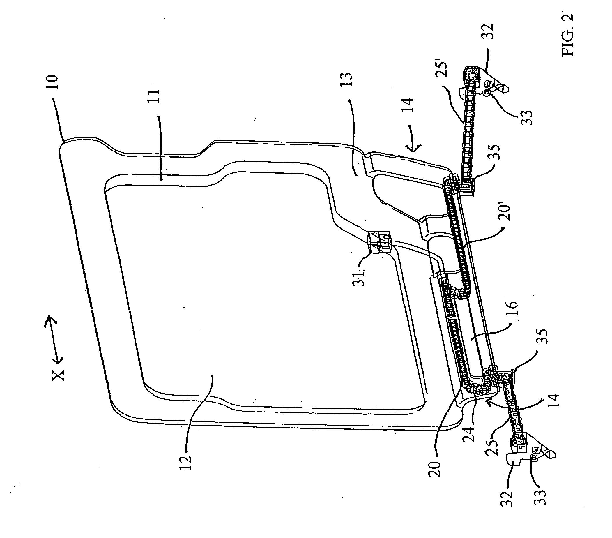
[0013] According to a further embodiment, the cable guide assembly comprises a first and a second section, whereby on moving the sliding door, the first section is only movable in the sliding plane including the longitudinal direction of the vehicle and whereby the second section is formed to be movable, especially pivotable, in a direction transverse to the sliding plane on relocating the sliding door into the sliding plane. Thus there exists a clear functional distinction between the cable compensation in the sliding plane or the longitudinal direction of the vehicle and the cable compensation in a direction transverse to the sliding plane which offers advantages in planning and assembly. Furthermore, it is ensured that the second section, which preferably spans the gap between the sliding door and the vehicle body, does not sag on relocating the sliding door and snag on obstacles projecting into the gap.
[0015] According to a further embodiment, in any position of the sliding door the cable guide assembly forms a substantially C-shaped turning area in which the direction in which the electric cables run is reversed. On moving the sliding door, this C-shaped turning area travels in the longitudinal direction of the vehicle inside the associated guide section. Thus the guide channel also fulfills a guiding function in order to limit the movement range of the C-shaped turning area on moving the sliding door. To reduce the friction forces in the completely open position and in the completely closed position of the sliding door, it is possible to provide that the C-shaped turning area is disposed outside the guide or in a widened end area of the guide channel in these sliding door positions.
[0017] According to a further embodiment, the guide or guide channel also includes a sliding element guide for guiding a sliding element which is connected to the cable guide assembly or is formed on it. The sliding element guide is preferably designed to guide the movement of the cable guide assembly in the longitudinal direction of the vehicle and to prevent a lateral evasive movement in a direction perpendicular to the longitudinal direction of the vehicle. This enables a separation of function in such a way that a first section of the cable guide assembly is exclusively responsible for compensating the displacement movement in the sliding plane parallel to the longitudinal direction of the vehicle, whilst a second section of the cable guide assembly is exclusively responsible for compensating movements of the cable guide assembly in a direction transverse to the sliding plane. Both sections of the cable guide assembly may be provided with cable guide elements formed to correspond with or differ from each other. For example, as is explained in greater detail in the following, the cable guide assembly responsible for compensation in the sliding plane may be formed as a cable drag chain, whilst the second cable guide assembly responsible for compensation in a direction transverse to the sliding plane may be designed as a flexible cable harness, also as a flexible cable duct or similar. This separation of function enables an even more flexible and cost-effective cable guiding concept.

Problems solved by technology

Supplying power to a sliding door is relatively complex since, unlike with a rotatably operable hinged door, where common points independent from the door's open condition are automatically specified between the vehicle body and the hinged door, no independent common points are provided between the vehicle body and the door by the door's open condition.
On opening the sliding door, the point of gravity moves backwards in the longitudinal direction of the vehicle, which makes the sliding movement difficult, especially for older or disabled people and especially on uneven ground.
This requires a reliable, uninterrupted supply of power to the drive motor.
The U-shaped, curved section of the cable harness spans the gap between the vehicle body and the sliding door, whereby there is no reliable way of preventing the cable harness from snagging.
This cable guiding concept requires additional provisions in the vehicle's roof liner which makes optional assembly of manually operated sliding doors and motor-driven sliding doors costly.

Method used


Image

  • Sliding door for motor vehicles and method for the assembly thereof
  • Sliding door for motor vehicles and method for the assembly thereof
  • Sliding door for motor vehicles and method for the assembly thereof

Examples


Embodiment Construction

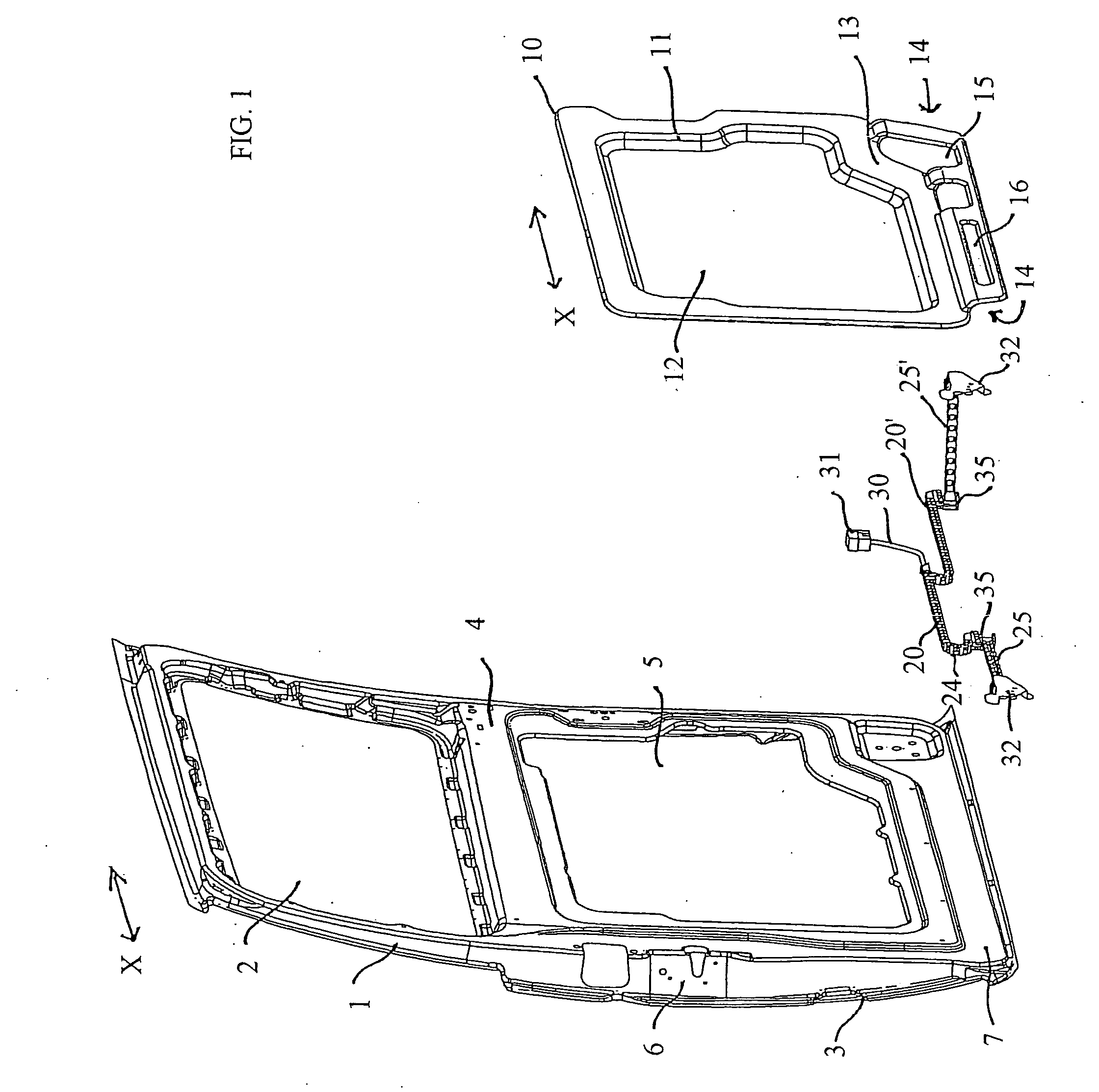
[0031] The left-hand part of FIG. 1 shows sliding door 1 that is formed by an outer door skin 3, which has a convex outward curve, and an inner door skin 4 and has a window aperture 2. The direction of movement extending parallel to the longitudinal direction of the vehicle is designated in the following by the double arrow x. On the rear face end of sliding door 1 is provided a door lock assembly 6. Inner door skin 4 forms a circumferential border which encloses a cavity 5 in sliding door 1, for example for lowering the window or for accommodating components. Sliding door 1 is supported in the known manner by means of articulated joints on guide rails which extend along the top and bottom edge of the vehicle's door aperture (not shown).

[0032] The right-hand part of FIG. 1 shows a plate-shaped door module support 10 which serves to accommodate a plurality of the sliding door's functional units. These functional units may be pre-assembled on door module support 10 prior to its insta...


PUM


Abstract

Sliding door for motor vehicles, having an outer door skin, an inner door skin and a door inside trim, supported on a guide rail on a vehicle body and which is movable between an opened and closed positions. The sliding door includes a cable guide assembly for accommodating and guiding electric cables, which connect first electric elements provided in or on the vehicle body to second electric elements provided on the sliding door, whereby on moving the sliding door, the cable guide assembly is movable in a plane including the longitudinal direction of the vehicle and whereby a guide channel for guiding the cable guide assembly is provided on moving the sliding door. Guide surfaces of the guide channel are formed or integrated at least in sections on the inner door skin, in a door module support and / or on the door inside trim.

Description

FIELD OF THE INVENTION [0001] The present invention relates to a sliding door for motor vehicles and a method for the manufacture thereof and especially relates to the transmission of electric power and / or electrical signals between a vehicle electrical system of a vehicle body and a sliding door. BACKGROUND OF THE INVENTION [0002] Supplying power to a sliding door is relatively complex since, unlike with a rotatably operable hinged door, where common points independent from the door's open condition are automatically specified between the vehicle body and the hinged door, no independent common points are provided between the vehicle body and the door by the door's open condition. There exists, therefore, the need to create an electrical connection between electrical elements located on the sliding door and on the vehicle body, which enable a permanent reliable transmission of voltage and / or signals regardless of the door's open condition. [0003] As is known, sliding doors are heavi...

Claims


Application Information

Patent Timeline
IPC IPC(8): E05F11/00
CPCH02G11/006B60J5/06
Inventor KUHNEN, THORSTENCRUZ, PATRICIAHERWIG, ARNDKRIESE, OLAF
Owner BROSE FAHRZEUGTEILE GMBH & CO KG
Learn More