Compressor piston ball pocket coating

Active Publication Date: 2007-07-12
MAHLE INT GMBH
View PDF13 Cites 12 Cited by
  • Summary
  • Abstract
  • Description
  • Claims
  • Application Information

AI Technical Summary

Benefits of technology

[0013] The invention described is a PTFE added polymer based piston ball pocket coating that can be used to replace the current technology of tin coating. This coating is well adhered to the substrate, and is able to provide high degree of self-lubrication at the friction surface. The coating's anti-galling properties are superio

Problems solved by technology

Under high-load and high-speed compressor operating conditions, the shoe transfers significant sliding wear load to the surface of the ball pocket.
This high sliding wear load can deform and/or tear the relatively soft aluminum alloy surface of the ball pocket.
Thus, galling or seizure at the shoe to the ball pocket interface can occur.
This galling tendency can be accelerated and made more severe under a lack of lubrication condition that can result in the failure of the compressor.
However, the tin coating has certain limitations.
First of all, the tin coating does not provide adequate protection against the galling tendencies under all circumstances.
In some situations, the tin coated/plated ball pocket remains the primary failure mode of the compressor during low/no oil operation.
A second limitation to the tin coating process is related to the environmental issues associated with process wastewater treatment.
The separation of heavy metal from the wastewater is difficult and costly.
In some manufacturing facilities, local environmental reg

Method used


Image

  • Compressor piston ball pocket coating
  • Compressor piston ball pocket coating
  • Compressor piston ball pocket coating

Examples


Embodiment Construction

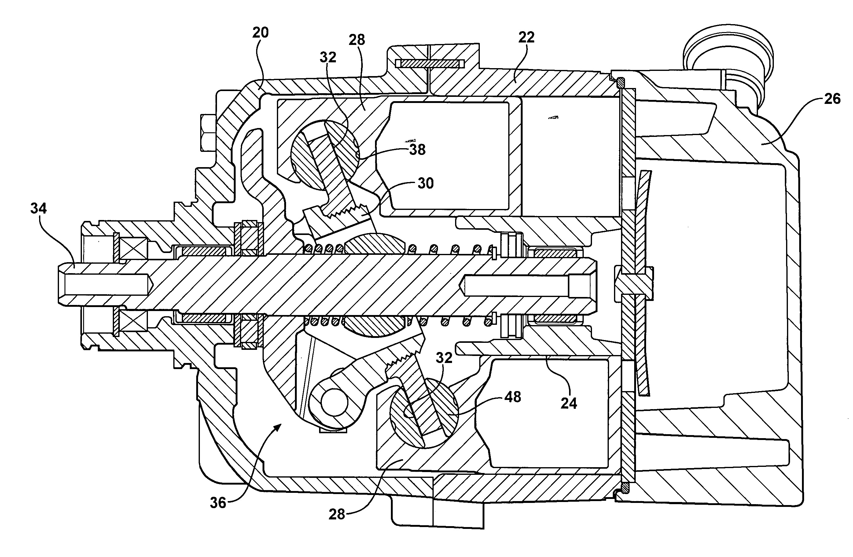
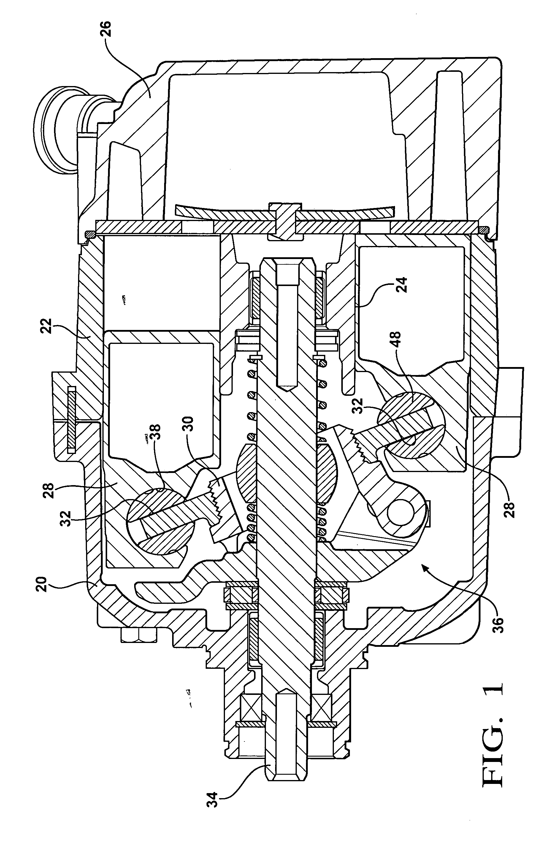
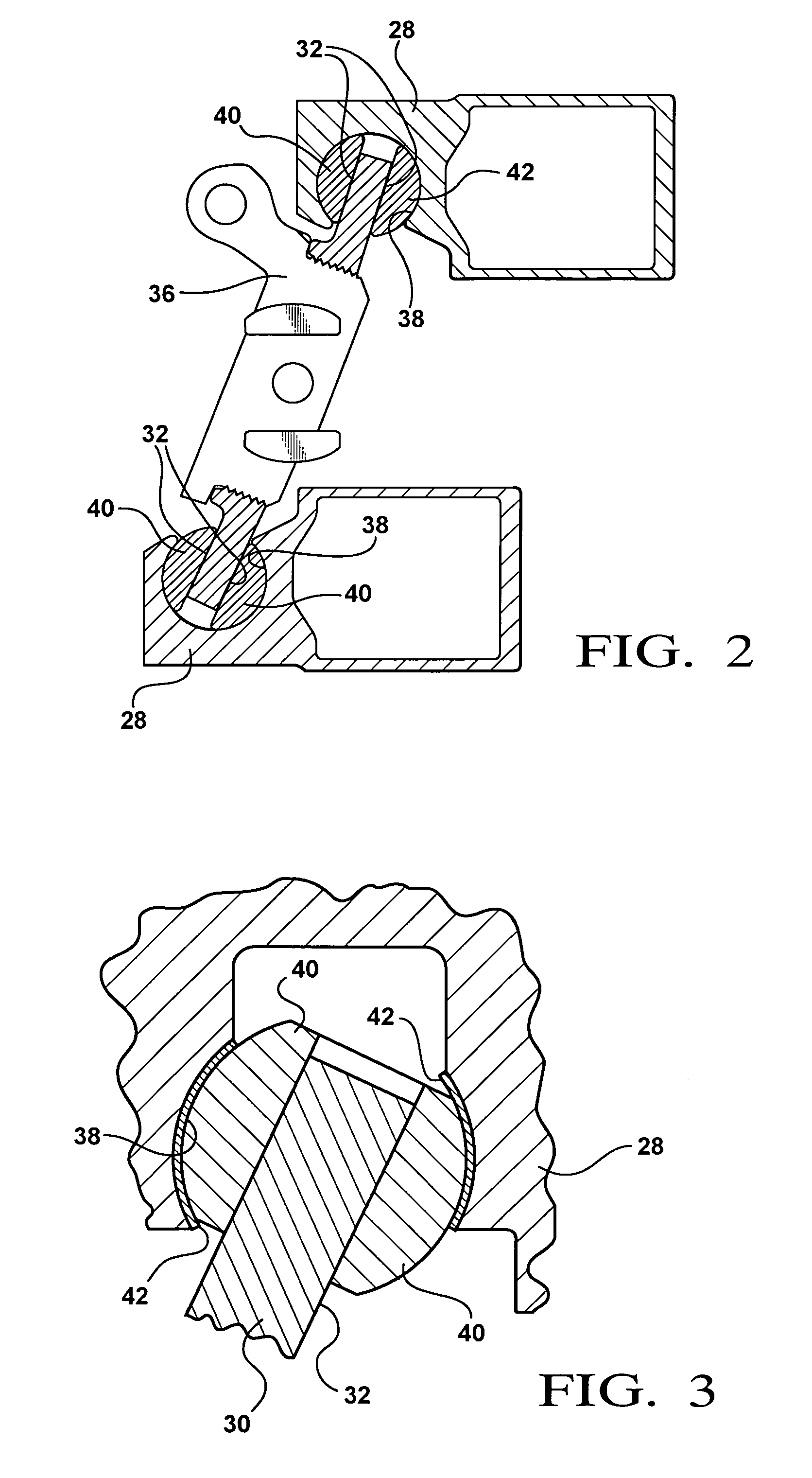
[0027] A compressor assembly with which the subject invention is utilized is generally shown in FIGS. 1, 2 and 3 typically include a housing 20 supporting a cylinder block 22 presenting a plurality of cylinder bores 24. A cap 26 closes an open end of the housing 20 and a plurality of bolts clamp the cylinder block 22 between the housing 20 and the cap 26. A piston 28 is disposed for reciprocation in each of the cylinder bores 24. The cylinder block 22 is usually an aluminum alloy.

[0028] A plate 30 presents a drive surface 32 extending transversely to the bores 24. This plate 30 is frequently referred to as a swash or wobble plate 30. A mechanism for effecting relative rotation between the cylinder block 22 and the plate 30 for reciprocating the pistons 28 in the cylinder bores 24 includes a drive shaft 34 rotatably supported by the housing 20 for rotation about an axis. The mechanism described also includes a pivot link 36 that allows the angle of the plate 30 to vary, setting the ...


PUM

PropertyMeasurementUnit
Fractionaaaaaaaaaa
Thicknessaaaaaaaaaa
Thicknessaaaaaaaaaa

Abstract

The invention is applied to a compressor assembly wherein a coating is applied to the pocket in the piston for sliding engagement with a shoe for reciprocating the piston. The coating is a composite of solid particles of a lubricant, suspended in an adhesive, bonded to the to the aluminum alloy defining the pocket. More specifically, the coating comprises particles of polytetrafluoroethylene (PTFE) suspended in an epoxy resin having a low cross-linking characteristic. The particles of PTFE are sub-micron in size and the ratio of PTFE to epoxy resin is optimally one to one. The thickness of the coating is between two and ten microns and preferably substantially four microns.

Description

BACKGROUND OF THE INVENTION [0001] 1. Field of the Invention [0002] A compressor assembly and method of fabricating the same wherein a coating interacts between pistons and the drive shoes that reciprocate the piston. [0003] 2. Description of the Prior Art [0004] In a swash plate type compressor used in air conditioning systems, the rotation of the swash plate is converted to the reciprocating movement of the pistons through respective shoes. The shoe is a semi-spherical part that has a flat surface in contact with the swash plate and spherical surface in contact with a ball pocket in the piston. In response to rotation of the angled swash plate, the shoe transfers the load to the piston, which forces the piston to move reciprocally in a cylinder as the spherical surface of the shoe slides against the ball pocket surface in the associated piston. Typically, the shoe is made from hardened steel and the piston is made from an aluminum alloy. Under high-load and high-speed compressor o...

Claims


Application Information

Patent Timeline
IPC IPC(8): F01B3/00
CPCF04B27/0886F05C2225/04F05C2253/20F05C2253/18F05C2251/14
Inventor COCHRAN, THEODORE R.ZHU, MINGGUANGGABEL, TIMOTHY M.
Owner MAHLE INT GMBH
Why Eureka
Try Eureka