Pneumatic hammer drill (I)
- Summary
- Abstract
- Description
- Claims
- Application Information
AI Technical Summary
Benefits of technology
Problems solved by technology
Method used
Image

Examples
Embodiment Construction
[0023] Before the present invention is described in greater detail, it should be noted that like elements are denoted by the same reference numerals throughout the disclosure.
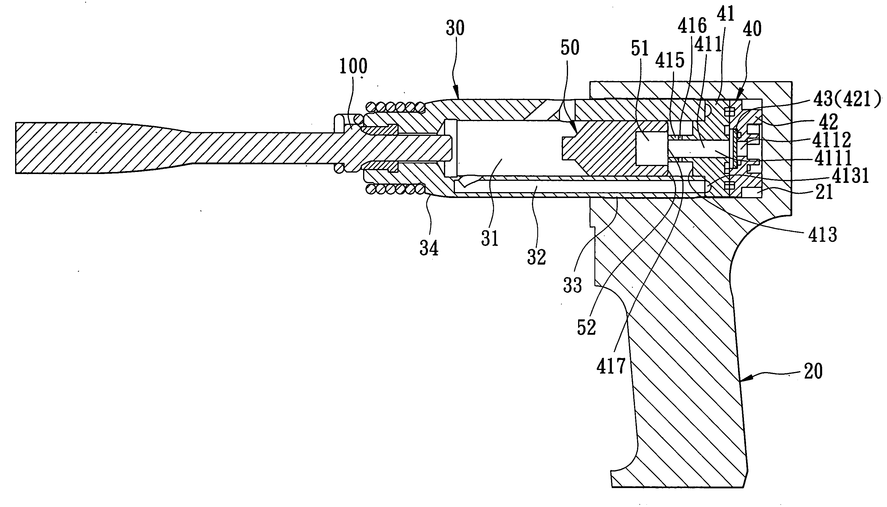
[0024] Referring to FIGS. 3 to 7, the first preferred embodiment of a pneumatic hammer drill according to the present invention is shown to comprise a handle body 20, a pneumatic cylinder 30, an air valve 40, a piston 50, and an air trap arrangement.
[0025] The handle body 20 defines a receiving space 21 at a top portion thereof. An air supply unit (not shown) is connected to a bottom end of the handle body 20 so as to introduce compressed air into the handle body 20.
[0026] The pneumatic cylinder 30 has a cylinder rear end 33 fitted in the receiving space 21, and a front tool-connecting end 34 extending outwardly of the receiving space 21 and adapted to connect with a tool 100, such as a chisel. The pneumatic cylinder 30 is provided with a pressure chamber 31, and an air passage 32.
[0027] The air valve 40 is...
PUM
 Abstract
Description
Claims
Application Information
 - R&D
- Intellectual Property
- Life Sciences
- Materials
- Tech Scout
- Unparalleled Data Quality
- Higher Quality Content
- 60% Fewer Hallucinations
Browse by: Latest US Patents, China's latest patents, Technical Efficacy Thesaurus, Application Domain, Technology Topic, Popular Technical Reports.
© 2025 PatSnap. All rights reserved.Legal|Privacy policy|Modern Slavery Act Transparency Statement|Sitemap|About US| Contact US: help@patsnap.com