Apparatus and adjusting method for a scanning transmission electron microscope

Inactive Publication Date: 2007-07-12
HITACHI HIGH-TECH CORP
View PDF2 Cites 48 Cited by
  • Summary
  • Abstract
  • Description
  • Claims
  • Application Information

AI Technical Summary

Benefits of technology

[0007] The present invention has been made in view of the above-mentioned circumstances. An object of the present inve

Problems solved by technology

Therefore, in the case where the multipole lens type spherical aberration corrector is mounted on the scanning transmission electron microscope, when the optical axis adjustment between the corrector and an electron microscope main

Method used


Image

  • Apparatus and adjusting method for a scanning transmission electron microscope
  • Apparatus and adjusting method for a scanning transmission electron microscope
  • Apparatus and adjusting method for a scanning transmission electron microscope

Examples


Example

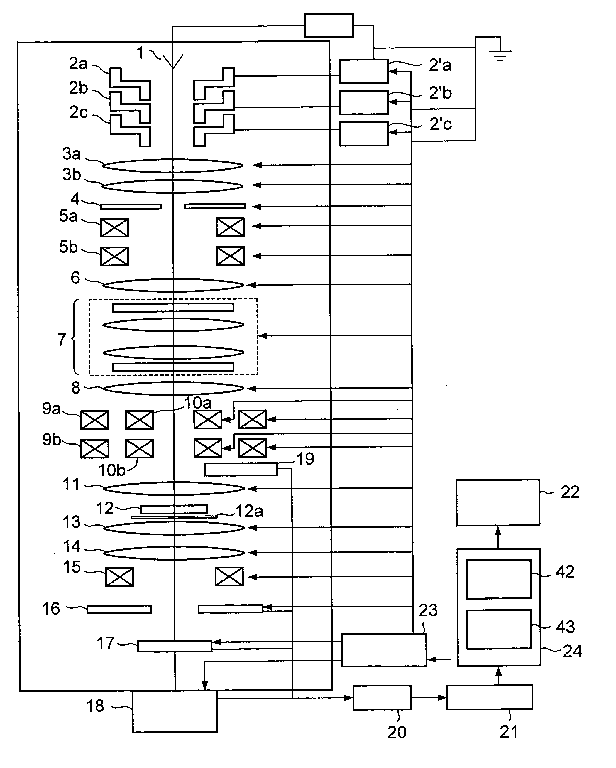
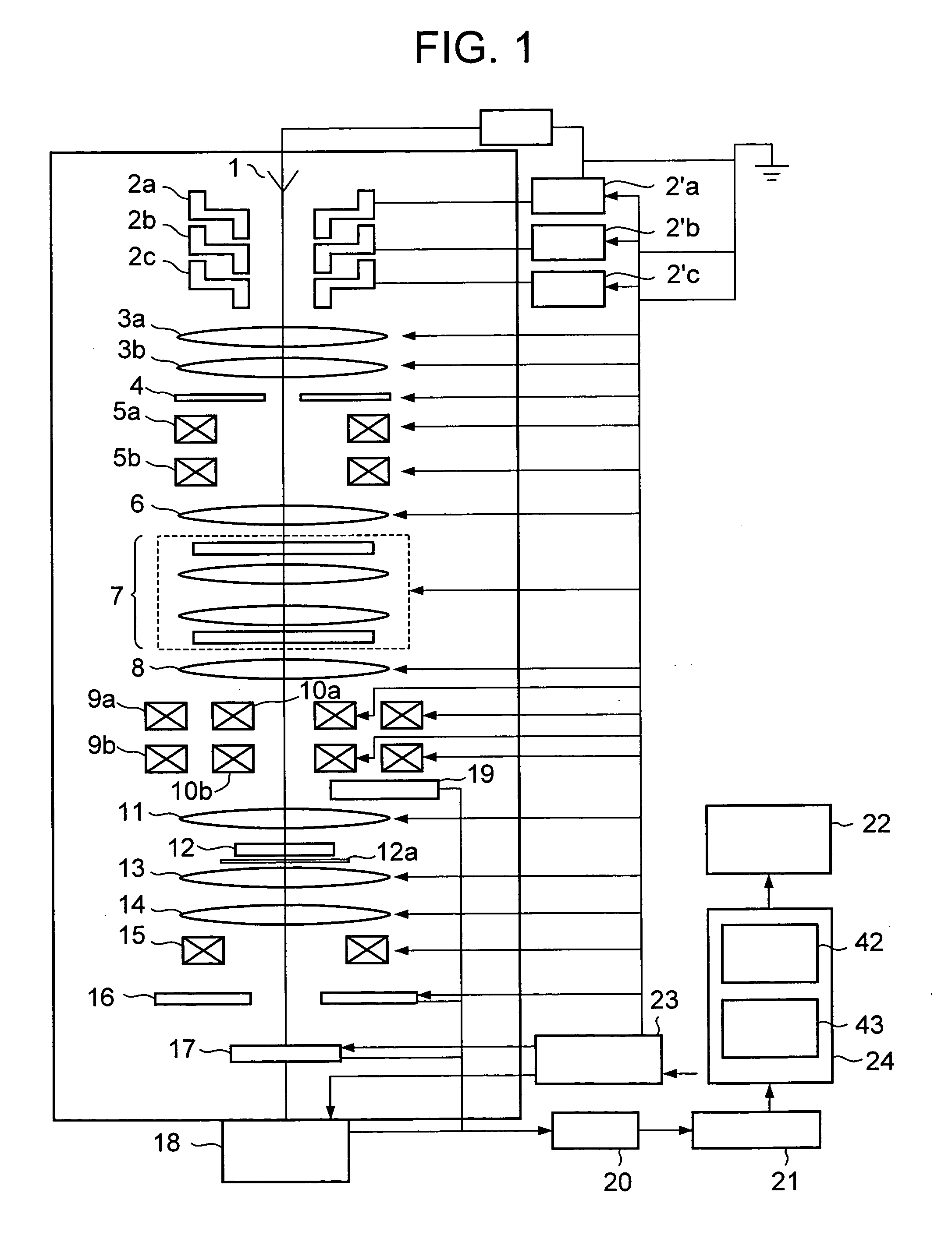
[0025]FIG. 1 is a schematic diagram showing a scanning transmission electron microscope according to a first embodiment of the present invention.

[0026] As shown in FIG. 1, the scanning transmission electron microscope according to this embodiment includes an electron beam source 1 which emits an electron, electrostatic lenses 2a to 2c, voltage control devices 2′a to 2′c which control voltages applied to the electrostatic lenses 2a to 2c, convergent lenses 3a and 3b, a convergent diaphragm 4 provided under the convergent lens 3b, an upper deflection coil 5a for corrector axis adjustment, a lower deflection coil 5b for corrector axis adjustment, an adjustment lens 6, a spherical aberration corrector 7, a transfer lens 8, an upper deflection coil 9a, a lower deflection coil 9b, scan coils 10a and 10b, a pre-magnetic field of objective lens 11, a specimen stage 12a on which a specimen 12 is placed, a post-magnetic field of objective lens 13, a projection lens 14, a detection system ali...

Example

Second Embodiment

[0085] In this embodiment, as against the first embodiment, for example, deflection fulcrums P1, P2, and P3 are set as shown in FIG. 9. Therefore, the operator can select a suitable set from a plurality of sets of Fourier transform images (display data) obtained at each of deflection ratios satisfying respective conditions. The schematic configuration of a scanning transmission electron microscope according to this embodiment is identical to that of the first embodiment as shown in FIG. 1.

[0086]FIG. 10 is an explanatory flowchart showing an operation flow, where the deflection ratio between the upper deflection coil 9a and the lower deflection coil 9b is adjusted in the scanning transmission electron microscope according to the second embodiment of the present invention.

[0087] Processing of Step S201 to S208 is identical to the processing of Step S101 to S108 as shown in FIG. 6. In this embodiment, the processor 42 further receives, from the operator through the ...

Example

Third Embodiment

[0099] In this embodiment, as against the first embodiment, the deflection ratio between the deflection coils 9a and 9b are automatically adjusted. Therefore, the processor 42 determines whether or not the degree of adjustment is suitable based on the plurality of Fourier transform images obtained before and after the beam shift. The schematic configuration of a scanning transmission electron microscope according to this embodiment is identical to that in the first embodiment as shown in FIG. 1.

[0100] In this embodiment, a deflection ratio between two dipole coils composing the deflection coils 9a and 9b is determined. Hereinafter, the case where the deflection coils 9a and 9b include two dipoles orthogonal to each other will be described.

[0101] First, a scanning transmission image is obtained without performing the beam shift and a Fourier transform image is produced therefrom. Next, the beam shift is performed by exciting only one of two dipole components compos...


PUM


Abstract

A scanning transmission electron microscope is provided including an electron beam source (1), convergent lenses (3), scan coils (10), a dark field image detector (16), a bright field image detector (17), an A/D converter (21), and an information processing device (24). In the scanning transmission electron microscope, a spherical aberration corrector (7) and deflection coils (9a, 9b) are disposed before a pre-magnetic field of objective lens (11). Fourier transform images are produced from scanning transmission images obtained by the dark field image detector (16) or the bright field image detector (17) to evaluate deviation in an aberration correction state due to an image shift caused by the deflection coils (9a, 9b) at a deflection ratio, so a suitable deflection ratio is fed back. As a result, an electron optics of the scanning transmission electron microscope including the corrector can be easily adjusted.

Description

CLAIM OF PRIORITY [0001] The present application claims priority from Japanese application JP 2005-371291 filed on Dec. 26, 2005, the content of which is hereby incorporated by reference into this application. BACKGROUND OF THE INVENTION [0002] The present invention relates to a scanning transmission electron microscope including a corrector, and more particularly, to a technique of adjusting a deflector of the scanning transmission electron microscope including the corrector. [0003] A scanning transmission electron microscope having an image shift function is known in the conventional art. The image shift function is realized using upper and lower deflection coils provided in an electron optics which scans a specimen with an electron beam. Specifically, the electron beam deflected by the upper deflection coil is deflected to a deflection fulcrum in a reverse direction by the lower deflection coil. Therefore, an electron beam irradiation position on the specimen is adjusted without ...

Claims


Application Information

Patent Timeline
IPC IPC(8): G21K7/00
CPCH01J37/1471H01J37/153H01J37/222H01J37/265H01J2237/2802H01J2237/1501H01J2237/1532H01J2237/1534H01J2237/223H01J37/28
Inventor NAKAMURA, TAISUKENAKAMURA, KUNIYASU
Owner HITACHI HIGH-TECH CORP
Why Eureka
Try Eureka