Backlight Unit

a backlight unit and backlight technology, applied in the field of backlight units, can solve the problems of low emission efficiency of white light leds, white light, high fabrication cost, etc., and achieve the effects of reducing manufacturing costs, reducing manufacturing costs, and ensuring color uniformity in display regions

Inactive Publication Date: 2007-07-12
INNOLUX CORP +1
View PDF3 Cites 11 Cited by
  • Summary
  • Abstract
  • Description
  • Claims
  • Application Information

AI Technical Summary

Benefits of technology

[0017] Preferably, the present invention matches the red LED chip, blue LED chip, and green LED chip with corresponding cyan compensation film, purple compensation film, and yellow compensation film to form a light emitting diode mixing package. Hence, by utilizing a much shorter light mixing distance, the present invention is able to eliminate the need of increasing the size of the light guide plate for generating white light beams as is required by the conventional technique. Additionally, the backlight unit of the present invention includes a sensor disposed on the light-exit plane of the light guide plate to measure the spectrum produced by the light emitting diode mixing package. Preferably, the present invention is able to utilize th

Problems solved by technology

However, even with white light LEDs many advantages, including: small sizes, high response speeds, low heat emissions, low consumptions of electric power, long lifetimes, high resistance to earthquakes, and low contamination, and are able to be flat packaged, the technique of developing white light LEDs, when compared to the common tungsten filament lamps or fluorescent lamps is not mature.
White light LED production techniques suffer from problems of high fabrication cost and low emission efficiency of the white light LEDs.
Therefore, white light LEDs are not commonly used in products.
The cost and efficiency of this method are low, and consequently this is t

Method used


Image

  • Backlight Unit
  • Backlight Unit
  • Backlight Unit

Examples


Embodiment Construction

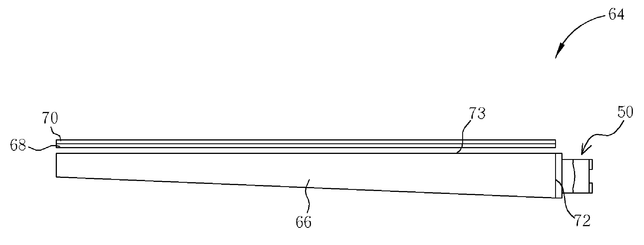
[0027] Please refer to FIG. 3. FIG. 3 is a perspective diagram showing the cross-section of a backlight unit 64 according to the present invention. As shown in FIG. 3, the backlight unit 64 includes a transparent light guide plate 66, a plurality of optical films 68 and 70, and at least a light emitting diode mixing package 50 utilized as a light source.

[0028] As shown in FIG. 3, one edge of the light guide plate 66 is a light-incidence plane 72, in which the light-incidence plane 72 is utilized for receiving the light generated by the light source. Additionally, a light-exit plane 73 formed on the top surface of the light guide plate 66, and a reflecting layer (not shown) is formed on the surface of the light guide plate 66 that is opposite to the light-incidence plane 72 and opposite to the light-exit plane 73, such that the light entering from the light-incidence plane 72 can only exit through the light-exit plane 73. Moreover, the optical films 68 and 70 disposed on the light-e...


PUM


Abstract

A backlight unit includes a light guide plate having a light-incidence plane and a light-exit plane and at least a light emitting diode (LED) mixing package located in proximity to the light-incidence plane for providing lights to the backlight unit. The LED mixing package includes at least a first color LED chip, at least a first color compensation film corresponding to the first color LED chip, at least a second color LED chip, and at least a second color compensation film corresponding to the second color LED chip, in which the first color compensation film and the second color compensation film are located on the light-incidence plane of the backlight unit. The backlight unit further includes at least a spectrum sensor disposed on the light-exit plane of the backlight unit.

Description

BACKGROUND OF THE INVENTION [0001] 1. Field of the Invention [0002] The invention relates to a backlight unit, and more particularly, to an LED light-mixing package of a backlight unit that produces white light. [0003] 2. Description of the Prior Art [0004] LEDs are widely applied as pilot lamps and light sources for various household appliances and instruments. This is due in part to the LEDs advantages, including: a long lifetime, small size, high resistance to earthquakes, low heat emission, and a low consumption of electric power. Additionally, development in recent years has resulted in LEDs that can produce rich color and high brightness. As a result, the LED is further applied in many kinds of movable electronic products. For example, the LED is utilized as a back light source for small-sized displays thereby becoming a source for a stream of illumination light having low power consumption and low contamination (i.e., radiation). [0005] Please refer to FIG. 1. FIG. 1 is a sch...

Claims


Application Information

Patent Timeline
IPC IPC(8): H01L33/00
CPCG02B6/0068G02B6/0026
Inventor YU, CHUAN-PEILI, RUI-YONG
Owner INNOLUX CORP
Why Eureka
Try Eureka