Composite magnet structure for rotor

a composite magnet and rotor technology, applied in the direction of magnetic circuits, electrical appliances, dynamo-electric machines, etc., can solve the problems of low flux density, low efficiency of motors, and low windage noise of motors at high speeds, so as to improve the life of the motor and quiet

Inactive Publication Date: 2007-07-12
EMERSON ELECTRIC CO
View PDF10 Cites 25 Cited by
  • Summary
  • Abstract
  • Description
  • Claims
  • Application Information

AI Technical Summary

Benefits of technology

[0006] Embodiments of the invention include IPM rotor designs with small air spaces and large slots in order to achieve a quiet motor and improved die life. Embodiments of the invention also include IPM rotor designs that demonstrate a near sinusoidal back EMF.

Problems solved by technology

The oversized slots allow air spaces around the neo which cause the motor to have high windage noise at high speeds.
This results in very small air spaces which correspond to a quieter motor.
The problem with ferrite is that it does not have a sufficiently high flux density to make an efficient motor.
Also, the die used in manufacturing this type of rotor has a short lifespan due to the small size of the neo slot.

Method used


Image

  • Composite magnet structure for rotor
  • Composite magnet structure for rotor
  • Composite magnet structure for rotor

Examples


Embodiment Construction

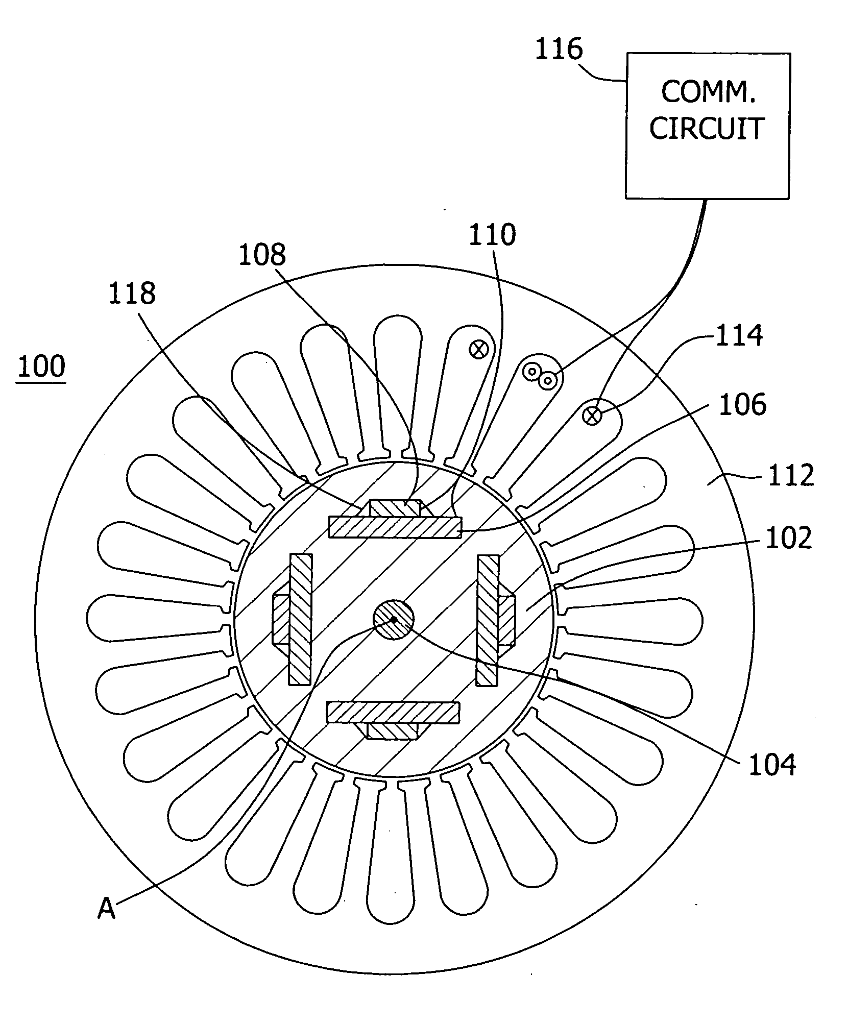
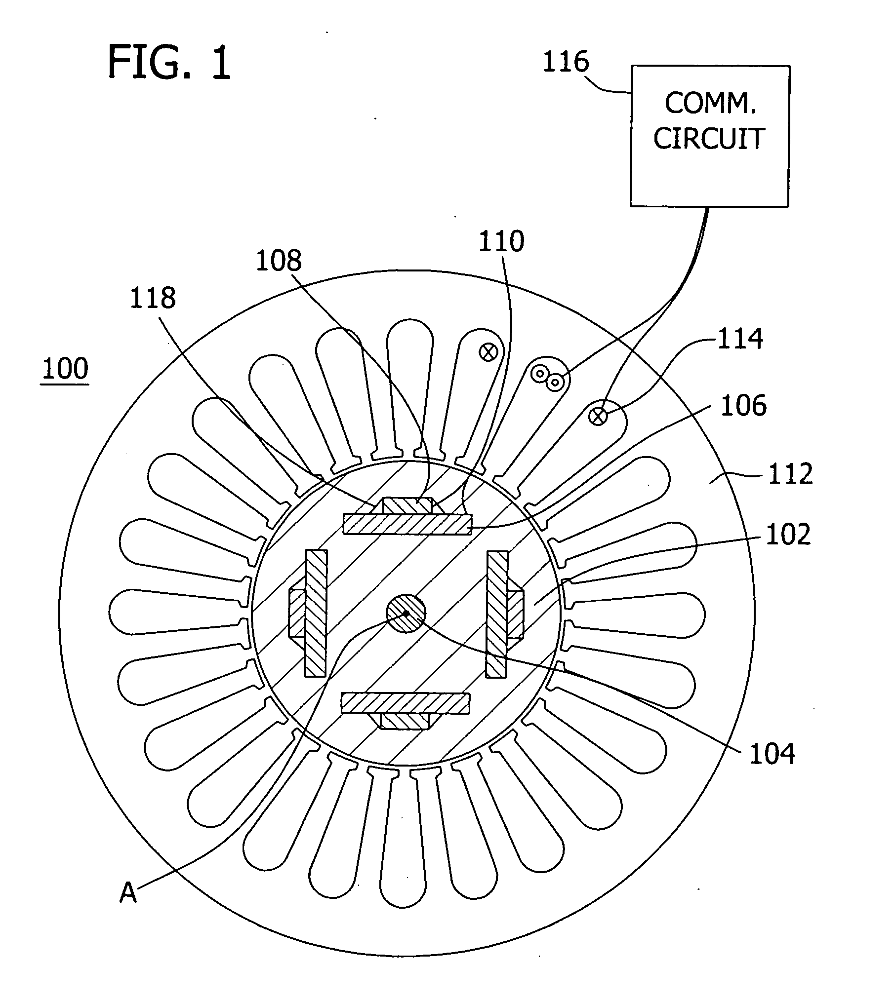
[0022] Referring to FIG. 1, one embodiment of a motor 100 of the invention is illustrated in cross section including a rotor 102 having a central shaft 104 rotating about an axis of rotation A. The rotor 102 comprises a cylindrical core of steel (or other material) having a slot 110 extending parallel to the shaft. Positioned within the slot 110 are a ferrite magnet 106 and a neo magnet 108. The rotor is positioned within a stator 112 having windings 114. The windings are connected to a commutation circuit 116. Commutation circuit 116 energizes the windings 114 causing the rotor 102 to rotate about the central shaft 104. FIG. 1 illustrates one embodiment in which a single, unitary slot 110 has located therein neo and ferrite magnets each having a generally rectangular cross section perpendicular to the axis of rotation A. The magnets each have a longer rectangular dimension which is generally parallel to each other and the ferrite magnet 106 is positioned between the neo magnet 108 ...


PUM


Abstract

An interior permanent magnet electric motor. A rotor comprising a slot radially spaced from its longitudinal axis of rotation extending parallel to the axis. First and second magnets are positioned in the slot and extend parallel to the axis. A first magnet is positioned between a second magnet and the axis.

Description

FIELD OF THE INVENTION [0001] The present invention generally relates to an electric motor rotor design. More particularly, the present invention relates to an interior permanent magnet rotor design wherein strontium ferrite and neodymium-iron-boron are positioned in a common slot in the rotor core. BACKGROUND OF THE INVENTION [0002] Interior permanent magnet (IPM) rotor designs using strontium ferrite (ferrite) and neodymium-iron-boron (neo) are known in the art. [0003] In one prior art design, the rotor has a core with long thin slots having neo in each slot. This design does not make use of ferrite. The slots are formed by using a punch press on the rotor core. In order to increase die life, decrease the core weight, and reduce flux leakage, the slots are oversized. The oversized slots allow air spaces around the neo which cause the motor to have high windage noise at high speeds. These motors can have a sinusoidal back electromagnetic flux (EMF) which is desirable. [0004] Anothe...

Claims


Application Information

Patent Timeline
Patent Type & Authority Applications(United States)
IPC IPC(8): H02K21/12
CPCH02K1/2766
Inventor HORST, GARY E.
Owner EMERSON ELECTRIC CO
Why Eureka
Try Eureka