Fluorescent lamp and manufacturing method thereof
a technology of fluorescent lamps and manufacturing methods, which is applied in the manufacture of electrode systems, discharge tubes with luminescent screens, discharge tubes, etc., can solve the problems of difficult to apply the technology disclosed in the patent to produce eefl, and the composition of metal oxides is not disclosed, so as to improve the lifetime and luminance of fluorescent lamps. , the effect of increasing the secondary electron emission ra
- Summary
- Abstract
- Description
- Claims
- Application Information
AI Technical Summary
Benefits of technology
Problems solved by technology
Method used
Image
Examples
first embodiment
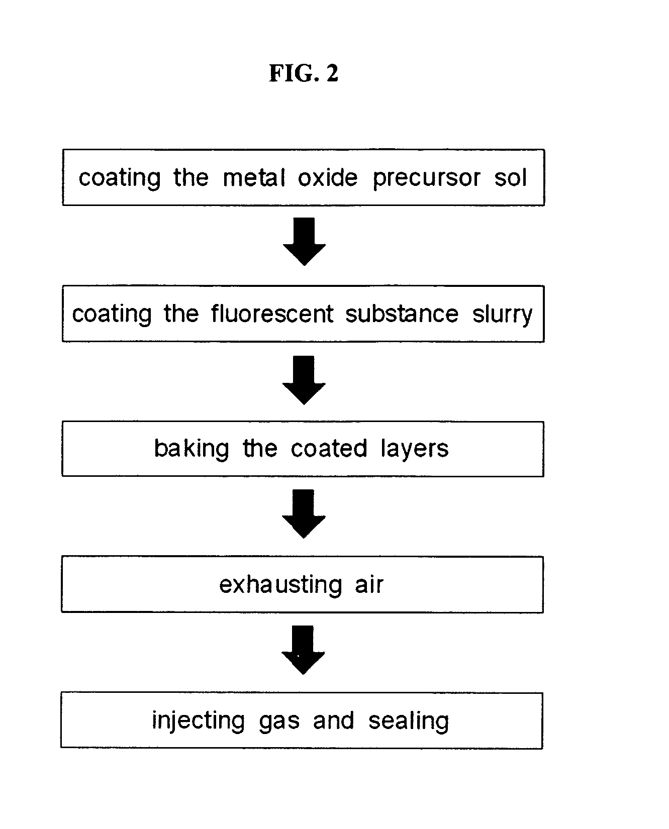
[0063]Referring FIG. 2, the dispersed metal oxide precursor is wet-coated on an entire surface of the inner wall of the glass tube of the EEFL (the first coating process), according to the present invention. Then, the fluorescent substance slurry is wet-coated on an entire surface of the dispersed metal oxide precursor, and passivation and fluorescent layers are formed simultaneously by baking the coated layers. Thereafter, the processes for exhausting the air from the inside of the glass tube, injecting the discharge gas, and sealing the glass tube are conducted, thereby completing the fluorescent lamp.
[0064]The coating of the dispersed metal oxide precursor and the fluorescent slurry may be conducted through dip coating, blade coating, slit coating, or spray coating.
[0065]FIG. 3 is a cross-sectional view of a fluorescent lamp according to a second embodiment of the present invention, and FIG. 4 is a flowchart illustrating a method of manufacturing the fluorescent lamp of FIG. 3. I...
third embodiment
[0069]FIG. 5 is a side sectional view of a fluorescent lamp according to the present invention, and FIG. 6 is a flowchart illustrating a method of manufacturing the fluorescent lamp of FIG. 5.
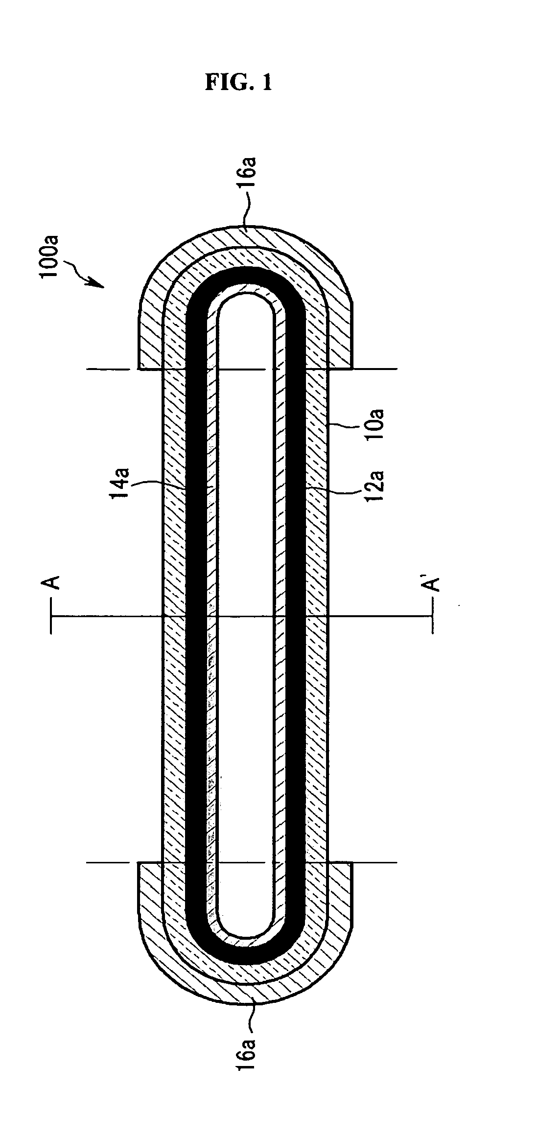
[0070]Referring to FIG. 5, an EEFL 100c of this third embodiment includes a passivation layer 12c on regions L and L′ of an inner wall of a glass tube 10c, which correspond to external electrodes 16c, and a fluorescent layer 14c is formed on an entire surface of the inner wall of the glass tube 10c covering the passivation layer 12c.
[0071]Since other components of the EEFL of this embodiment are identical to those of the fluorescent lamp of FIG. 1, the detailed description thereof will be omitted herein.
[0072]Referring to FIG. 6, in order to manufacture the EEFL of this embodiment, a metal oxide sol is coated on the regions L and L′ (the first coating process), and a fluorescent slurry is coated on the entire surface of the inner wall of the glass tube to cover the metal oxide sol coated on th...
fourth embodiment
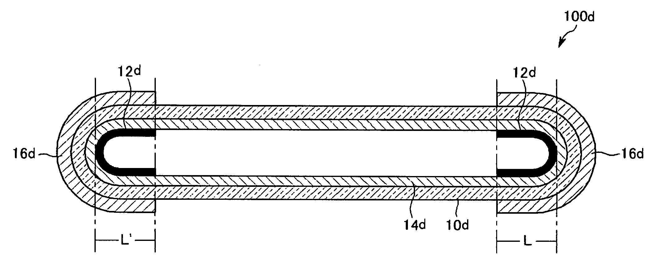
[0073]FIG. 7 is a side sectional view of an EEFL according to the present invention.
[0074]Referring to FIG. 7, unlike the EEFL 10c of FIG. 3, in an EEFL 100d of this fourth embodiment of the present invention, a fluorescent layer 14d is formed on an entire surface of an inner wall of a glass tube 10d, and a passivation layer 12d is formed on regions L and L′ of the fluorescent layer 14d, which correspond to lengths of external electrodes 16d.
[0075]Since other components of the EEFL of this embodiment are identical to those of the fluorescent lamp of FIG. 1, the detailed description thereof will be omitted herein.
[0076]Referring to FIG. 8, in order to manufacture the fluorescent lamp of this embodiment, a fluorescent slurry is first coated on the entire surface of the inner wall of the glass tube (the first coating process). Then, a metal oxide sol is coated on the regions L and L′ of the fluorescent slurry coated on the entire surface of the inner wall of the glass tube (the second...
PUM
| Property | Measurement | Unit |
|---|---|---|
| Temperature | aaaaa | aaaaa |
| Fraction | aaaaa | aaaaa |
| Percent by mass | aaaaa | aaaaa |
Abstract
Description
Claims
Application Information
 - R&D
- Intellectual Property
- Life Sciences
- Materials
- Tech Scout
- Unparalleled Data Quality
- Higher Quality Content
- 60% Fewer Hallucinations
Browse by: Latest US Patents, China's latest patents, Technical Efficacy Thesaurus, Application Domain, Technology Topic, Popular Technical Reports.
© 2025 PatSnap. All rights reserved.Legal|Privacy policy|Modern Slavery Act Transparency Statement|Sitemap|About US| Contact US: help@patsnap.com


