Core exhaust mixer, having a variable area, for turbo-fan jet engines of supersonic aircraft

a turbo-fan and mixer technology, applied in the direction of machines/engines, mechanical equipment, transportation and packaging, etc., can solve the problems of significant lengthening of the jet engine, significant noise reduction, and contradictory requirements, so as to reduce the noise level of the jet engine during takeoff and small overall dimensions

Active Publication Date: 2007-07-19
SN DETUDE & DE CONSTR DE MOTEURS DAVIATION S N E C M A
View PDF17 Cites 9 Cited by
  • Summary
  • Abstract
  • Description
  • Claims
  • Application Information

AI Technical Summary

Benefits of technology

[0008] It is therefore a principal object of the present invention to mitigate such drawbacks by proposing a core exhaust mixer having a variable area, which makes it possible to reduce the jet noise level of the jet engine during takeoff, with small overall dimensions.
[0010] The use of lobes having an azimuthal component substantially assists mixing of the air flow, external to the jet engine, and the gas flow from the gas generator (mixing of cold and hot flows). Indeed, the swirling of the air which is generated by this particular shape of the lobes increases the shearing effects existing in the convergence zone between cold and hot flows from the gas generator. With identical acoustical performance, it is thus possible to shorten the length of the jet engine (and thus decrease its weight) compared to a jet engine provided with a traditional mixer. In the same way, with the same length of jet engine, it is possible to reduce the jet noise during takeoff compared to a jet engine provided with a traditional mixer.

Problems solved by technology

However, these two requirements are contradictory.
As the jet noise increases with the ejection speed of the gases, reduction in this speed generates a significant drop in noise level during takeoff.
Although satisfactory, this solution is disadvantageous in that significant lengthening of the jet engine is required in order to assist mixing of the external air flow and the gas flow from the gas generator.
However, the jet engine is lengthened to the detriment of its size.

Method used


Image

  • Core exhaust mixer, having a variable area, for turbo-fan jet engines of supersonic aircraft
  • Core exhaust mixer, having a variable area, for turbo-fan jet engines of supersonic aircraft
  • Core exhaust mixer, having a variable area, for turbo-fan jet engines of supersonic aircraft

Examples


Embodiment Construction

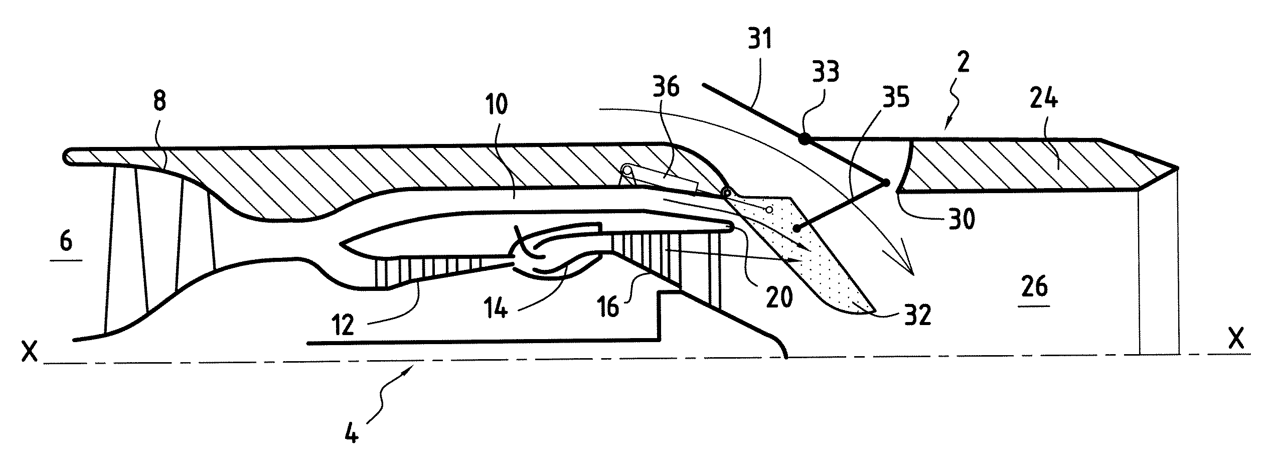
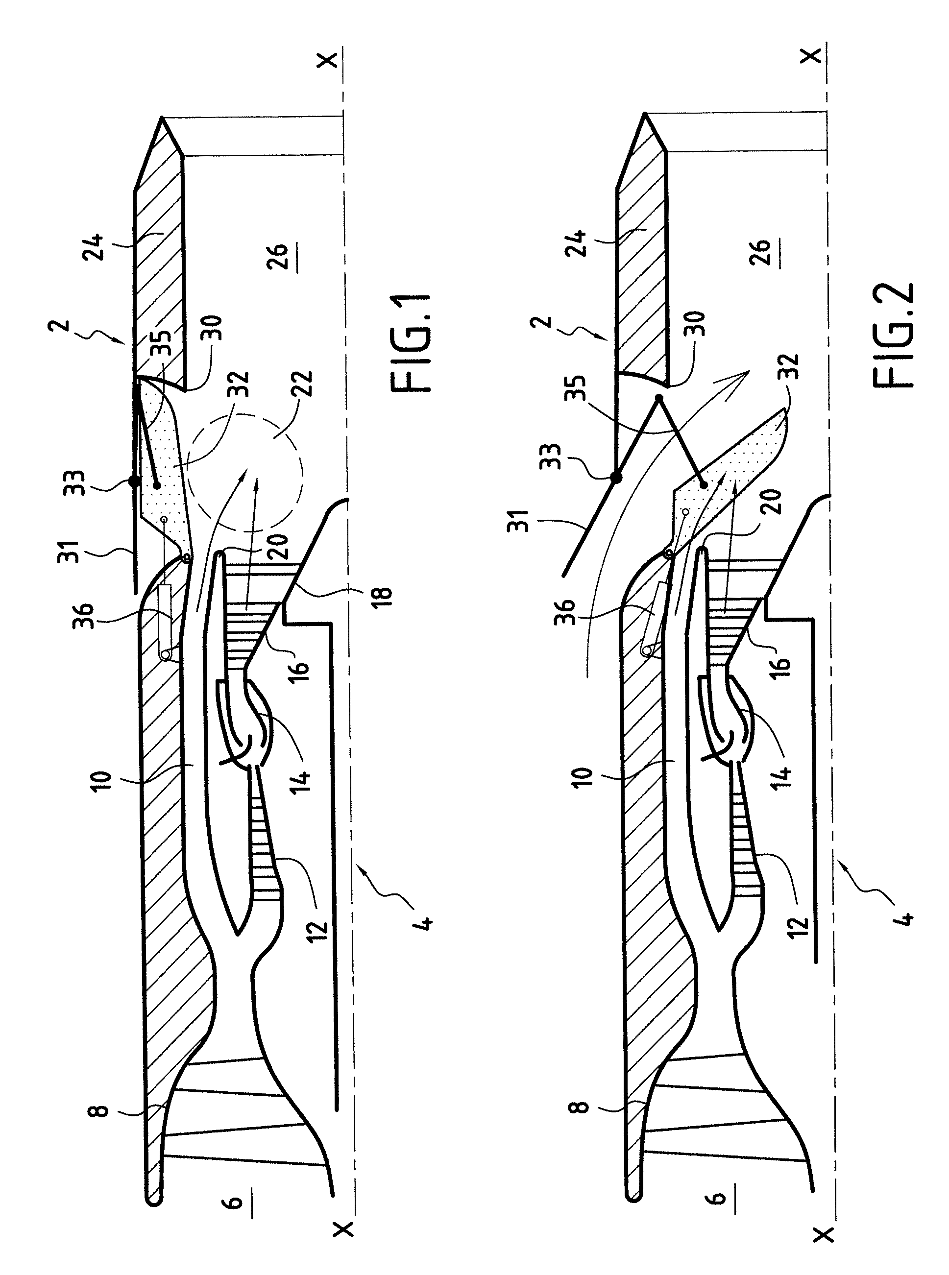
[0021]FIGS. 1 and 2 are semi-views in longitudinal section of a turbo-fan jet engine with low by-pass ratio for supersonic aircraft.

[0022] A jet engine 2 of this kind is composed primarily of a gas generator 4 with longitudinal axis X-X partially illustrated in FIGS. 1 and 2.

[0023] In a manner known per se the latter has an air intake 6, a low pressure compressor 8 feeding air partly to a cold flow exhaust passage 10 and partly to a high-pressure compressor 12.

[0024] At the exit of the high-pressure compressor 12, the compressed air is mixed with fuel in a combustion chamber 14 and ignited there. The gases resulting from this combustion drive a turbine 16, before being evacuated through hot flow exhaust passage 18.

[0025] An annular ring 20 separates the cold flow exhaust passage 10 from the hot flow exhaust passage 18. Downstream of this ring, cold and hot flows mix in a zone 22 called the convergence zone.

[0026] The jet engine also comprises a substantially cylindrical nozzle ...


PUM


Abstract

The invention relates to a core exhaust mixer, having a variable area, for turbo-fan jet engines of supersonic aircraft, comprising a nozzle (24) intended to be arranged about a gas generator of the jet engine, the nozzle comprising a plurality of external air intake apertures (30) emerging in a convergence zone between cold and hot flows from the gas generator and in which lobes (32), movable between two positions, are mounted; a first position in which they block the apertures (30) of the nozzle (24) and a second position, different from the first, in which they unblock said apertures and extend radially into the nozzle (24) in order to admit external air, the lobes (32) having an azimuthal component in the same direction in order to give a swirling motion to the external air admitted into the convergence zone when the lobes are in the second position.

Description

BACKGROUND OF THE INVENTION [0001] The present invention relates to the general field of core exhaust mixers, having a variable area, for turbo-fan jet engines with low by-pass ratio for supersonic aircraft. [0002] A turbo-fan jet engine with low by-pass ratio for supersonic aircraft is composed primarily of a dual-flow gas generator (cold flow and hot flow) prolonged by a nozzle, which defines a gas ejection passage. [0003] Turbo-fan jet engines with low by-pass ratio equipping supersonic aircraft, which are intended for civil aviation, must meet two requirements: on the one hand, they must have the lowest possible drag in flight during transonic and supersonic cruising, and on the other hand, they must have an acceptable noise level during takeoff of the aircraft, the certification authorities being increasingly demanding as regards sound emissions from the jet engines of civil aircraft. [0004] However, these two requirements are contradictory. In fact, the first requirement leads...

Claims


Application Information

Patent Timeline
Patent Type & Authority Applications(United States)
IPC IPC(8): F02K3/02
CPCF02K1/36F05D2260/96Y02T50/671F02K1/383Y02T50/60
Inventor DUSSILLOLS, LAURENTVUILLEMIN, ALEXANDRE ALFRED GASTON
Owner SN DETUDE & DE CONSTR DE MOTEURS DAVIATION S N E C M A
Why Eureka
Try Eureka