Thermosiphon having improved efficiency

Inactive Publication Date: 2007-07-19
NOVEO TECH
View PDF0 Cites 31 Cited by
  • Summary
  • Abstract
  • Description
  • Claims
  • Application Information

AI Technical Summary

Benefits of technology

[0026] The present invention increases the heat transfer obtained by the thermosiphon to such a level that it becomes a viable alternative to costlier heat pipes, thermal wheels and direct air heat exchangers. Furthermore, the thermosiphon does not require geometrical constraints that may be inconvenient such as with heat pipes and thermal wheels that require the exhaust and intake ducts to be side-by-side. Since it operates with gra

Problems solved by technology

Hence, thermosiphons necessitate minimal maintenance, further contributing to their cost-effectiveness.
Although a very interesting product, existing thermosiphons are often overlooked for many applications because the heating they produced is not important enough to justify their use.
This is due to their inherent design limitations.
Unfortunately, for an application such as transferring heat from air evacuated from a building, pool boiling is not very effective.
Consequently, the rate of evaporation is relatively low, impairing the efficiency of the thermosiphon.
Howev

Method used


Image

  • Thermosiphon having improved efficiency
  • Thermosiphon having improved efficiency
  • Thermosiphon having improved efficiency

Examples


Example

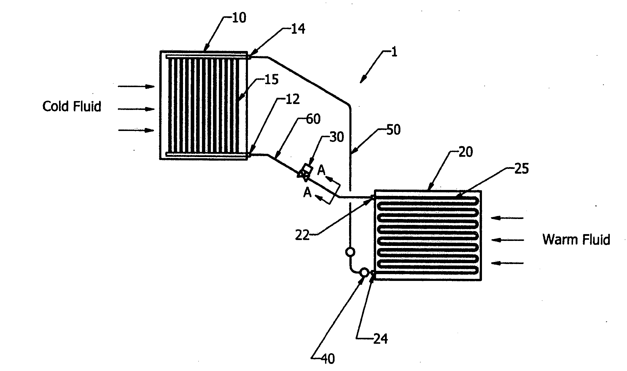
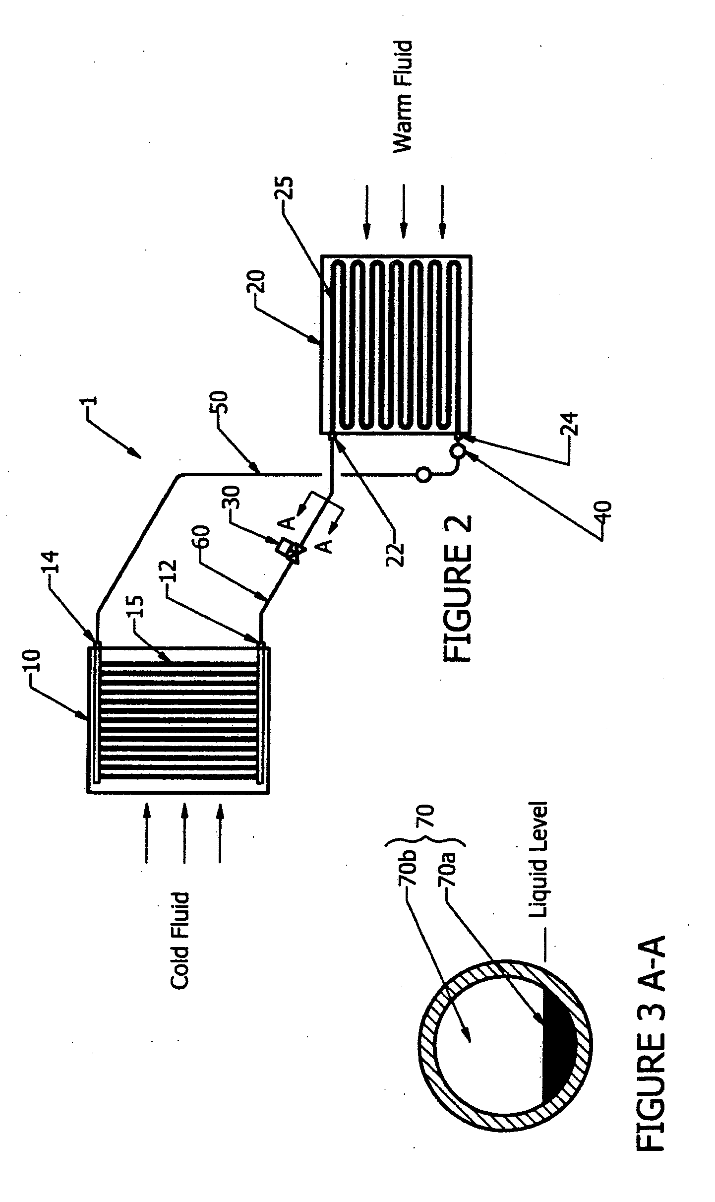
[0035]FIG. 2 shows the thermosiphon 1 of the present invention. The thermosiphon 1 contains a fluid 70, which is best seen in FIG. 3, under two different phases: liquid 70a and gaseous 70b. When the thermosiphon is not functioning, the liquid fluid 70a rests at the bottom of an evaporator 20. When functioning, the evaporator 20 exchanges heat by convection with the surrounding warm fluid that moves through it. As the liquid fluid 70a starts to evaporate and becomes gaseous, it exits evaporator outlet 24 and rises via the conduit 50 to the condenser 10 through its inlet 14. Since condenser 10 also exchanges heat by convection with the surrounding cold fluid that moves through it, the gaseous fluid 70b condensates on the walls of the condenser 10. By gravity, the liquid fluid 70a falls to the bottom of the condenser 10 where it exits through the condenser outlet 12. Normally in a thermosiphon, to further save energy by not having to use a pump, the condenser outlet 12 is located highe...


PUM


Abstract

The invention relates to an improved thermosiphon and to a method for transferring heat. The thermosiphon has a higher efficiency than existing thermosiphons because it does not rely on a pool-boiling evaporator but rather uses a forced-convection boiling evaporator. The inlet of the evaporator is located in its upper portion and is in fluid communication with a condenser. The fluid in its liquid phase enters the evaporator from its inlet in its upper portion and, by gravity, flows down the piping network of the evaporator, clinging on the inner surface of the tubes of the piping network. As the liquid flows down, it evaporates such that the fluid at the bottom of the evaporator is predominantly in a gaseous phase. The fluid in gaseous phase is then returned to the condenser.

Description

FIELD OF THE INVENTION [0001] The present invention generally relates to the field of heat exchangers. More particularly, the invention relates to an improved thermosiphon. BACKGROUND OF THE INVENTION [0002] A thermosiphon is a type of heat exchanger. The thermosiphon induces movement in a fluid by creating density gradients in the fluid through the exchange of heat. Currents are then generated by gravity as denser regions in the fluid tend to fall and the lighter ones tend to rise. [0003] A closed-loop thermosiphon is one that forms a closed circuit within which the fluid circulates. The fluid is heated in one part of the circuit. If the density of the fluid varies inversely with temperature—which is generally the case—the heating causes it to rise to another part of the circuit that is cooled. The heated fluid releases its heat in this cooled part of the circuit. The circulating fluid then falls back down to the heated part of the circuit to start the cycle once again. [0004] The ...

Claims


Application Information

Patent Timeline
IPC IPC(8): F28D15/00
CPCF28D15/06F28D15/0266
Inventor DIONNE, JEAN-PIERRELAGANA, ANTONIO
Owner NOVEO TECH
Why Eureka
Try Eureka