Observation apparatus with focal position control mechanism

a control mechanism and observation apparatus technology, applied in the direction of mountings, instruments, measurement devices, etc., can solve the problems of reducing productivity or operational efficiency, fatigue of operators, and affecting the operation, so as to improve the focusing stability inside the imaging area, the effect of preferably adjusting and shortening the tim

Inactive Publication Date: 2007-07-19
OLYMPUS CORP
View PDF3 Cites 19 Cited by
  • Summary
  • Abstract
  • Description
  • Claims
  • Application Information

AI Technical Summary

Benefits of technology

[0027] This observation apparatus with the focal position control mechanism can automatically adjust or select the most appropriate diaphragm diameter with respect to the imaging area, and it is possible to preferably adjust in short time.
[0028] In accordance with the present invention, it is possible to improve a focusing stabilit...

Problems solved by technology

If operability is not effective or preferable, there is a bad influence such as fatigue on the operator, lower productive or operational efficiency, and the like.
As shown in FIG. 8B, light is scattered at the edge portion close to the level difference of the object under inspection, that is, a ...

Method used


Image

  • Observation apparatus with focal position control mechanism
  • Observation apparatus with focal position control mechanism
  • Observation apparatus with focal position control mechanism

Examples


first embodiment

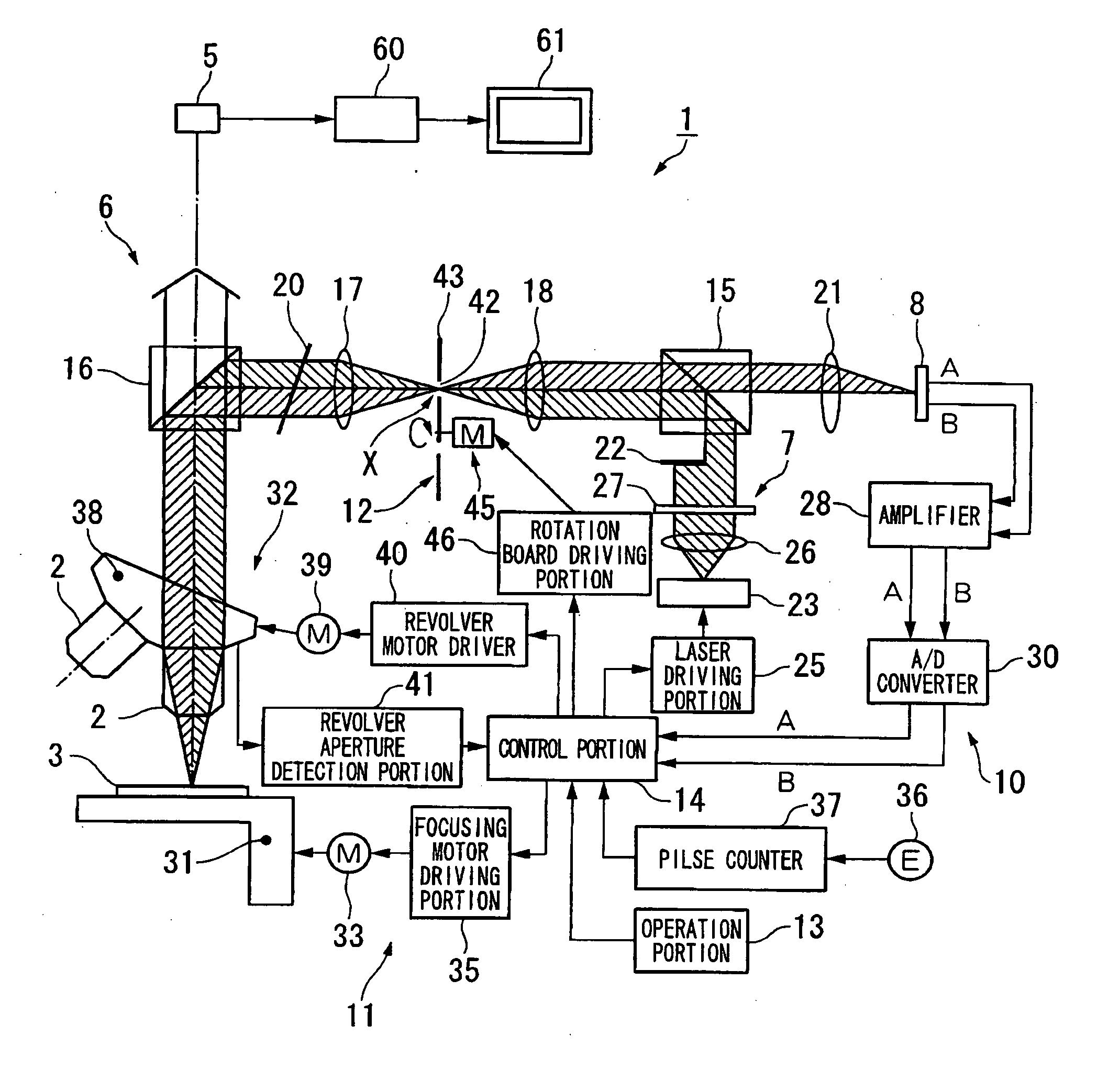
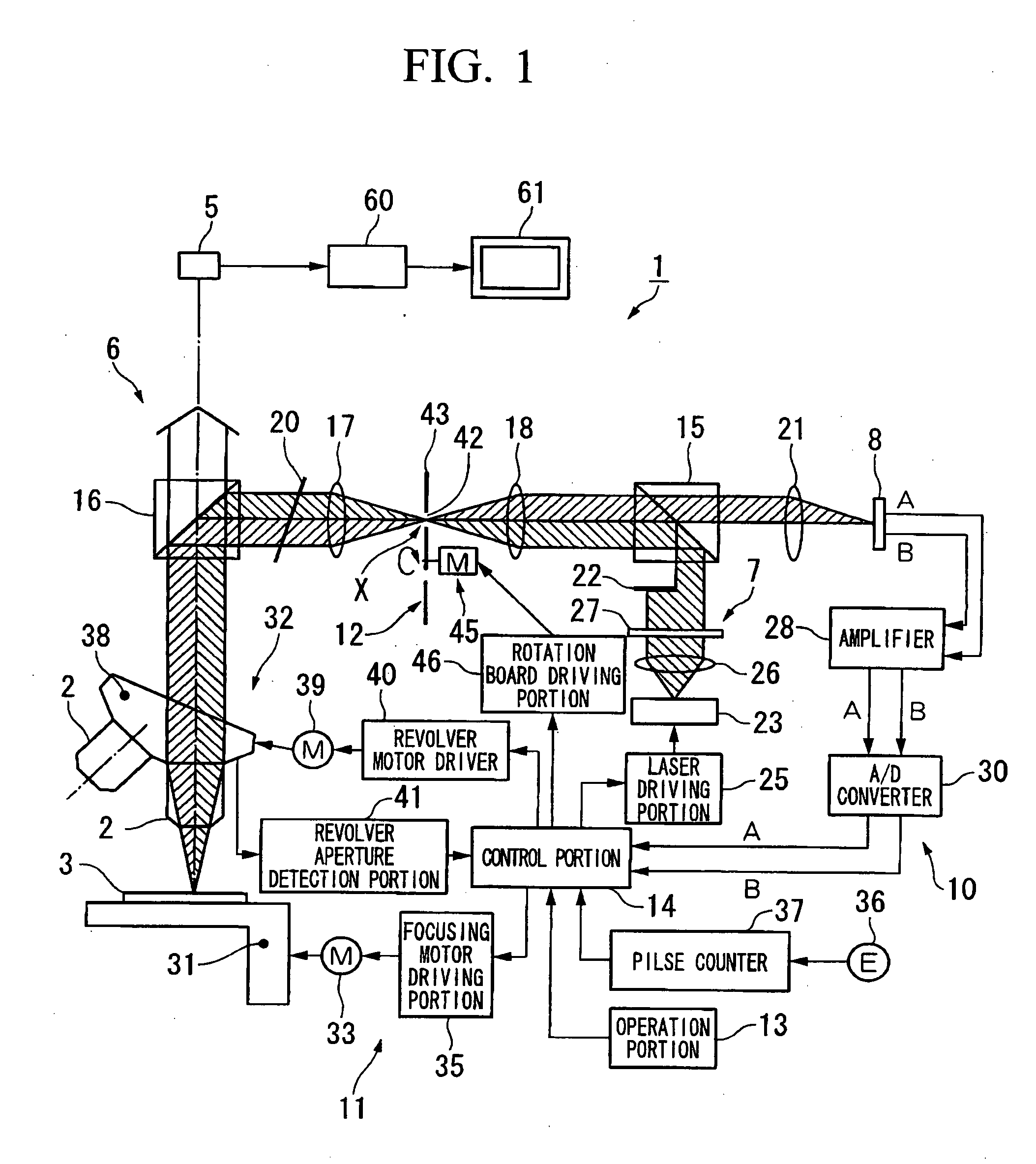
[0048] Referring to FIGS. 1-4, the present invention is explained.

[0049] As shown in FIG. 1 an AF apparatus for a microscope of this embodiment includes: an observational optical system 6 which radiates light on an object under inspection 3 via one of multiple interchangeable objective lens 2 and which has a CCD (imaging device) 5 for observing reflected light from the object under inspection 3; a light flooding portion 7 which radiates a laser (non-visible light) of infrared wavelength on the object under inspection 3 via the objective lens 2 of the observational optical system 6; a focal point detection optical system 10 which has a photo-detector (photo-electric conversion portion) 8 that is arranged at an image surface of a light figure of the reflected laser from the object under inspection, output signals corresponding to a position of the light figure inside the image surface, and detects the relative distance between the objective lens 2 and the object under inspection 3; an...

second embodiment

[0072] Next, referring to FIG. 5, a second embodiment is explained.

[0073] It should be noted that with respect to the same constitutional elements described in the first embodiment, the same reference numerals are assigned and explanations are omitted.

[0074] One difference between the second embodiment from the first embodiment is that the AF apparatus for microscope 50 of this embodiment provides, for example: an adjustable diaphragm 52 such as a blade diaphragm applied to a camera and the like which can adjust the diaphragm diameter; an adjustable diaphragm motor 53 which drives the adjustable diaphragm 52; and an adjustable diaphragm driving portion 55 which drives this adjustable diaphragm motor 53.

[0075] Moreover, a control portion 56 is provided so as to be able to adjust the diaphragm diameter of the adjustable diaphragm 52 based on an output signal from the object position adjusting unit 11.

[0076] In this AF apparatus for the microscope 50, the control portion 56 detects ...

third embodiment

[0079] Next, referring to FIG. 6, a third embodiment is explained.

[0080] It should be noted that with respect to same constitutional elements described in the above-described embodiments, the same reference numerals are assigned and the explanations are omitted.

[0081] One difference between the third embodiment and the second embodiment is that the adjustable diaphragm 52 of an AF apparatus for a microscope 60 of this embodiment is arranged at a position Y between the object under inspection 3 and the object lens 2,

[0082] By applying this AF apparatus for microscope 60, the adjustable diaphragm 52 is arranged at a position at which a bundle of laser is converged. Therefore, as described in the second embodiment, it is possible to more preferably limit the length of the radiated spotlight of the laser so as to be inside the imaging area 48 because the diaphragm of the adjustable diaphragm 52 is adjustable.


PUM


Abstract

An AF apparatus for a microscope (1) of the present invention includes: an observational optical system (6) which radiates light on an object under inspection (3) via one of multiple interchangeable objective lens (2) and which has a CCD (imaging device) (5) for observing reflected light from the object under inspection (3); a light flooding portion (7) which radiates a laser (non-visible light) on the object under inspection (3) via the objective lens (2) of the observational optical system (6); a focal point detection optical system (10) which has a photo-detector (photo-electric conversion portion) (8) that is arranged at an image surface of a light figure of the reflected laser from the object under inspection and that outputs signals corresponding to the position of the light figure inside the image surface, and which detects the relative distance between the objective lens (2) and the object under inspection (3); an object position adjusting unit (11) which adjusts the focal position of the object under inspection (3) based on the output signals from the focal point detection optical system (10); and a diaphragm unit (12) which adjust the area on which the laser is radiated so as to be inside the imaging area of the CCD (5).

Description

BACKGROUND OF THE INVENTION [0001] 1. Field of the Invention [0002] The present invention relates to an observation apparatus with a focal position control mechanism. [0003] Priority is claimed on Japanese Patent Application No. 2004-269669, filed Sep. 16, 2004, the content of which is incorporated herein by reference. [0004] 2. Description of Related Art [0005] These days, an observation apparatus such as a microscope which can be used to observe a minute sample under inspection or which can record the observed image onto a video is widely used in fields ranging from biological research to the inspection steps of industrial manufacture. In general, in the case in which such a microscope is used, a focusing operation is conducted in order to adjust the focus on the observed sample by operating a focusing handle. However, especially in a case of a shallow focal depth and a narrow focal range, such as a high-power objective lens, experience and skill is required for conducting quick f...

Claims


Application Information

Patent Timeline
IPC IPC(8): G02B27/40
CPCG02B21/247
Inventor KURATA, SHUNSUKETSUJI, HARUYUKI
Owner OLYMPUS CORP
Why Eureka
Try Eureka