Electronic cooling system having a ventilating duct

a cooling system and electronic technology, applied in the direction of electrical apparatus casings/cabinets/drawers, semiconductor/solid-state device details, instruments, etc., can solve the problems of deteriorating the operational stability of the cpus, affecting the cooling effect, and generating a lot of heat for many computer electronic devices such as central processing units (cpus) during normal operation. to achieve the effect of cooling

Inactive Publication Date: 2007-07-19
FU ZHUN PRECISION IND SHENZHEN +1
View PDF8 Cites 30 Cited by
  • Summary
  • Abstract
  • Description
  • Claims
  • Application Information

AI Technical Summary

Benefits of technology

[0005] According to a preferred embodiment of the present invention, a heat dissipation device in a computer enclosure comprises a heat spreader thermally connected with a CPU mounted on a printed circuit board of the computer, a first heat sink, a cooling fan coupled to the first heat sink, a second heat sink, a heat pipe mounted on the heat spreader and thermally connected the first heat sink and the second heat sink, a system fan attached to the second heat sink, and a fan duct interconnected between the cooling fan and the second heat sink, such that an airflo

Problems solved by technology

Many computer electronic devices such as central processing units (CPUs) generate a lot of heat during normal operation.
The heat can deteriorate the operational stability of the CPUs and damage the associated computers.
The above-mentioned conventional heat dissipation system is increasingly unable to meet the demanding heat-removal requirement of the contemporary CPUs.
The conventional heat dissipation sys

Method used


Image

  • Electronic cooling system having a ventilating duct
  • Electronic cooling system having a ventilating duct
  • Electronic cooling system having a ventilating duct

Examples


Embodiment Construction

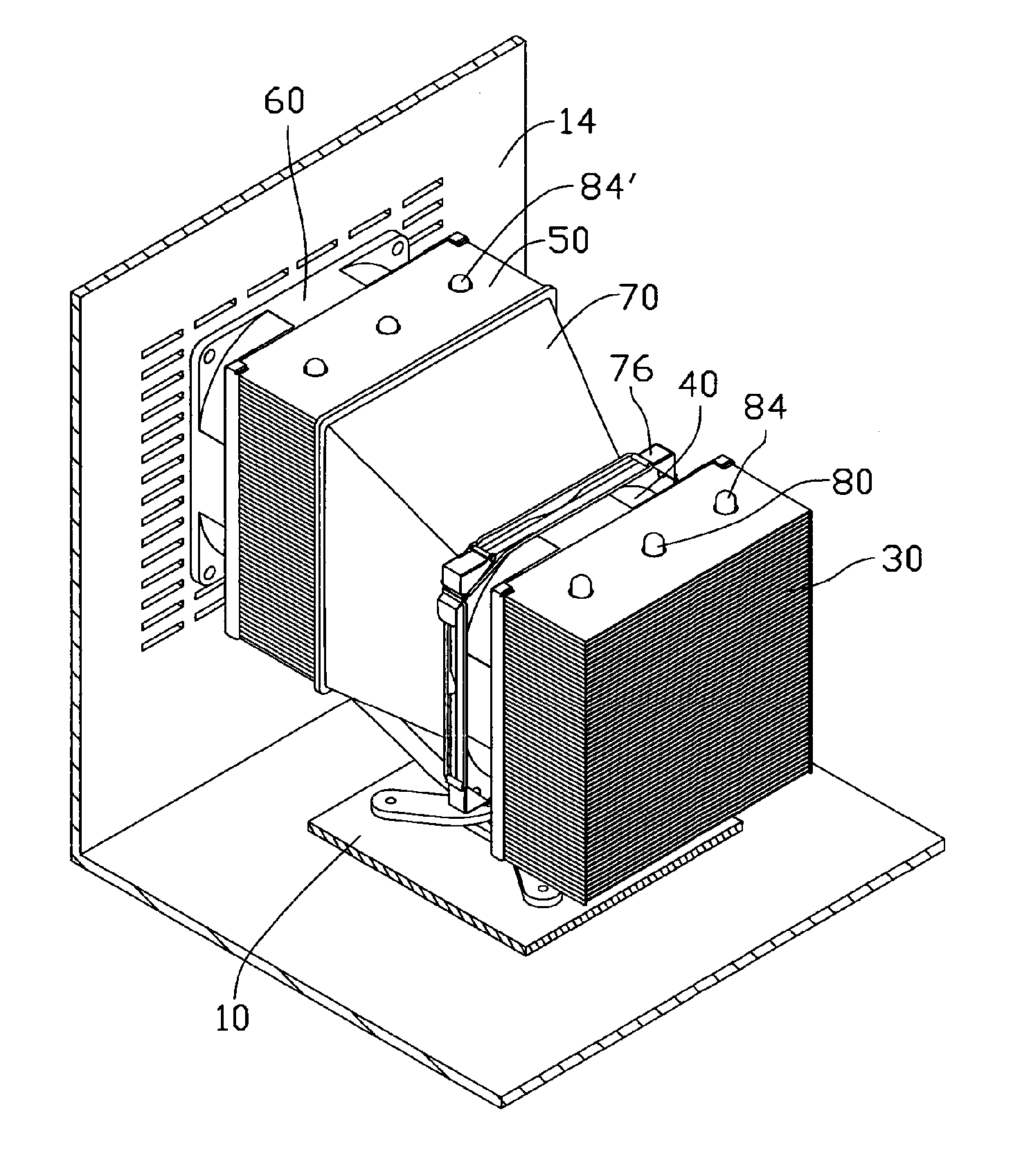
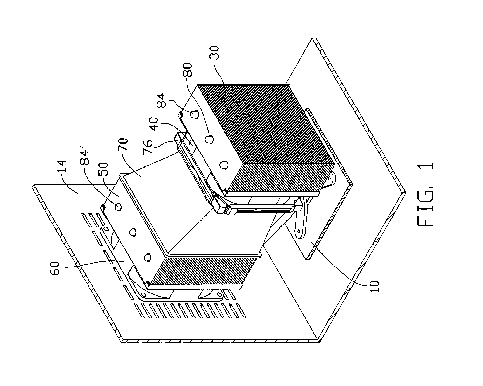
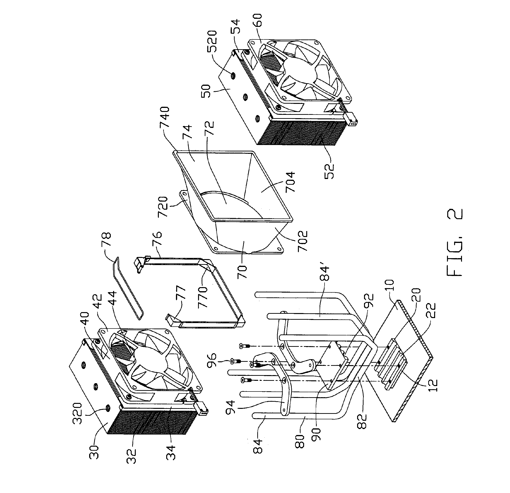
[0009]FIG. 1 and FIG. 2 show a heat dissipation device of the present invention which is installed onto a printed circuit board (PCB) 10 of a computer enclosure 14 of a computer. A central processing unit (CPU) 12 is mounted on the PCB 10. The heat dissipation device comprises a heat spreader 20 attached on the CPU 12, a first heat sink 30, a cooling fan 40 coupled to the first heat sink 30, a second heat sink 50, a system fan 60 attached to the second heat sink 50, a fan duct 70 interconnected between the cooling fan 40 and the second heat sink 50, and three juxtaposed heat pipes 80 positioned on the heat spreader 20 and thermally connecting the first heat sink 30 with the second heat sink 50.

[0010] The heat spreader 20 is made of metal material such as copper or aluminum, with good heat conductivity, for absorbing heat generated by the CPU 12. The heat spreader 20 defines three slots 22 at a top portion thereof, for receiving the heat pipes 80. Each of the heat pipes 80 has a sub...


PUM


Abstract

A heat dissipation device in a computer enclosure includes a heat spreader (20) mounted on a CPU (12), a first heat sink (30), a cooling fan (40) coupled to the first heat sink, a second heat sink (50), a heat pipe (80) mounted on the heat spreader and thermally connected the first heat sink and the second heat sink, a system fan (60) attached to the second heat sink, and a fan duct (70) interconnected between the cooling fan and the second heat sink. The system fan is positioned adjacent to louvers of the computer enclosure. An airflow generated by the cooling fan and the system fan flows through the first heat sink, then the fan duct, the second heat sink, and finally the louvers to leave the computer enclosure.

Description

FIELD OF THE INVENTION [0001] The present invention relates to a heat dissipation device in a computer enclosure, and particularly to a heat dissipation device having a ventilating duct to guide an airflow generated by a cooling fan of the heat dissipation device out of the computer enclosure. DESCRIPTION OF RELATED ART [0002] Many computer electronic devices such as central processing units (CPUs) generate a lot of heat during normal operation. The heat can deteriorate the operational stability of the CPUs and damage the associated computers. Thus, the heat must be removed efficiently to ensure the normal operation. Conventionally, a heat sink is attached to a top surface of a CPU in a computer to remove heat therefrom. A cooling fan is often attached on a top of the heat sink, for generating a forced airflow through the heat sink to help a quick removal of the heat from the heat sink. A system fan is often attached on a rear panel of the computer to expel the heat dissipated from ...

Claims


Application Information

Patent Timeline
IPC IPC(8): G06F1/20
CPCG06F1/20H01L23/427H01L23/467H01L2924/0002H01L2924/00
Inventor CHEN, CHUN-CHIWUNG, SHIH-HSUNYU, GUANGZHOU, DA-YUANLIU, JIN-BIAO
Owner FU ZHUN PRECISION IND SHENZHEN
Why Eureka
Try Eureka