Electrodynamic electroacoustic transducer and electronic device

a transducer and electroacoustic technology, applied in the direction of transducer details, electrical transducers, electrical apparatus, etc., can solve the problems of deformation of performance and increase in the volume of the electroacoustic transducer itself, and achieve the effect of improving the magnetic flux density, high performance and the same thickness

Active Publication Date: 2007-07-19
PANASONIC CORP
View PDF3 Cites 50 Cited by
  • Summary
  • Abstract
  • Description
  • Claims
  • Application Information

AI Technical Summary

Benefits of technology

[0049] According to the first aspect described above, the structure is such that the first magnetic pole part and the second magnetic pole part do not overlap with each other in the vibrating directions of the diaphragm. Thus, when an electrodynamic electroacoustic transducer is to be implemented that has the same thickness, the magnet included in at least one of the first magnetic pole part and the second magnetic pole part can be constructed thicker in the vibrating directions than in the conventional art. This improves the magnetic flux density at the voice coil position, and hence realizes an electrodynamic electroacoustic transducer of high performance that has the same thickness as the conventional one. Further, in a magnet fabricated from neodymium used generally in a small / thin speaker, high temperature demagnetization occurs more easily for a magnet having a higher energy product. However, when the magnet is made thicker according to this configuration, the permeance coefficient increases so that the magnet becomes resistive against high temperature demagnetization. Thus, with increasing the temperature reliability or alternatively maintaining the same temperature reliability, a magnet having a higher energy product can be employed. This improves further the magnetic flux density at the voice coil position, and hence realizes a small and thin electrodynamic electroacoustic transducer of higher performance. Further, with maintaining the temperature reliability in the conventional art, a thin electrodynamic electroacoustic transducer can be realized that has been impossible according to the conventional art magnetic circuit structure. Further, according to the present invention, an electrodynamic electric sound transducer is adopted so that a driving primary coil is not employed that has caused a reduction in the magnetic flux density in the magnetic gap in the electromagnetic induction type electroacoustic transducer according to the conventional art. Thus, the present invention provides a high performance electroacoustic transducer having the same thickness as the conventional one.
[0050] According to the second aspect described above, the lower face of the second magnetic pole part is located above the upper face of the first magnetic pole part, while a magnetic gap is formed between both magnetic poles. In order to implement a thin electrodynamic electroacoustic transducer, the second magnetic pole part can be arranged in an oblique direction relative to the first magnetic pole part in some cases. However, even in this case, since the magnetic flux in the magnetic gap has a component perpendicular to both of the winding direction and the amplitude direction of the voice coil, the diaphragm can be driven. Thus, an electrodynamic electroacoustic transducer can be implemented that has a thickness reduced in comparison with the conventional art.
[0051] According to the third aspect described above, the lower face of the second magnetic pole part is located below the upper face of the first magnetic pole part or alternatively in plane. Thus, when the thickness of the electrodynamic electroacoustic transducer itself is the same, the thicknesses of both magnetic pole parts can be increased in the vibrating directions in comparison with the case that the lower face of the second magnetic pole part is located above the upper face of the first magnetic pole part. This provides an advantage in improving the performance of the electrodynamic electroacoustic transducer.
[0052] According to the fourth aspect described above, among the first magnetic pole part and the second magnetic pole part, a magnetic pole part that does not include a magnet can be constructed from a magnetic material such as iron other than a magnet. Thus, cost reduction is expected. Further, the magnetic pole part not including a magnet can be made thin. This provides an advantage in the thickness reduction of the electrodynamic electroacoustic transducer.
[0053] According to the fifth aspect described above, the magnets included in the first magnetic pole part and the second magnetic pole part have the same polarity in the vibrating directions of the diaphragm. This allows magnetization to be performed after the assembling of the electrodynamic electroacoustic transducer, and hence provides an advantage in the fabrication in comparison with the case that the two magnets are magnetized in the opposite directions. Further, when magnets are provided in both parts, the magnetic flux density in the gap is increased. This provides an advantage in improving the performance of the electrodynamic electroacoustic transducer.
[0054] According to the sixth aspect described above, the first magnetic pole part is an annular body where an open space is formed. The open space provides an effect of allowing sound from the lower face of the diaphragm to escape downward easily. Further, examples of the annular body of the second magnetic pole part include a circle, an ellipse, and a polygonal annular body.

Problems solved by technology

Nevertheless, the increase in the volume of the magnet causes an increase in the volume of the electroacoustic transducer itself.
Thus, a problem arises that the performance is degraded.

Method used


Image

  • Electrodynamic electroacoustic transducer and electronic device
  • Electrodynamic electroacoustic transducer and electronic device
  • Electrodynamic electroacoustic transducer and electronic device

Examples


first embodiment

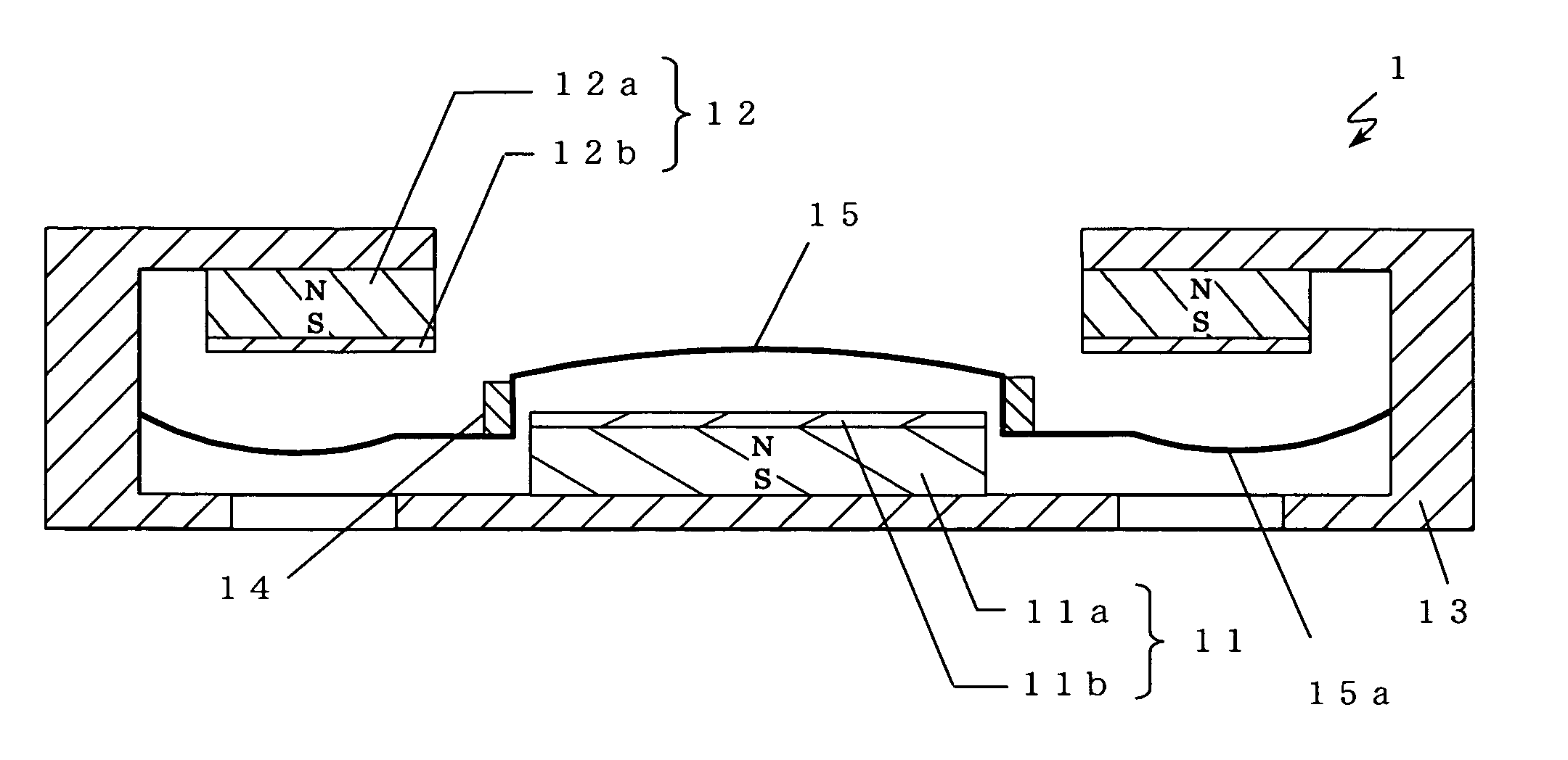
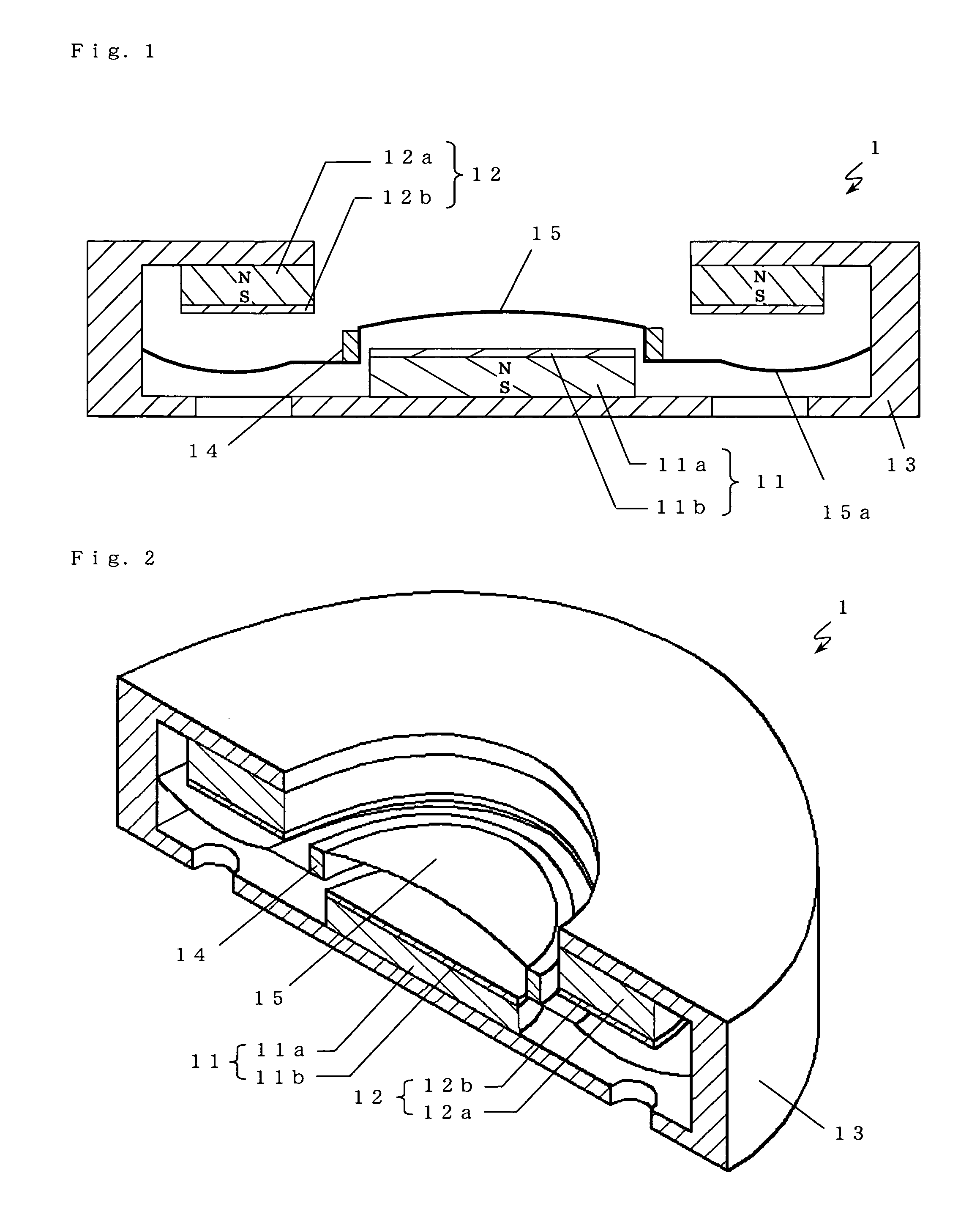
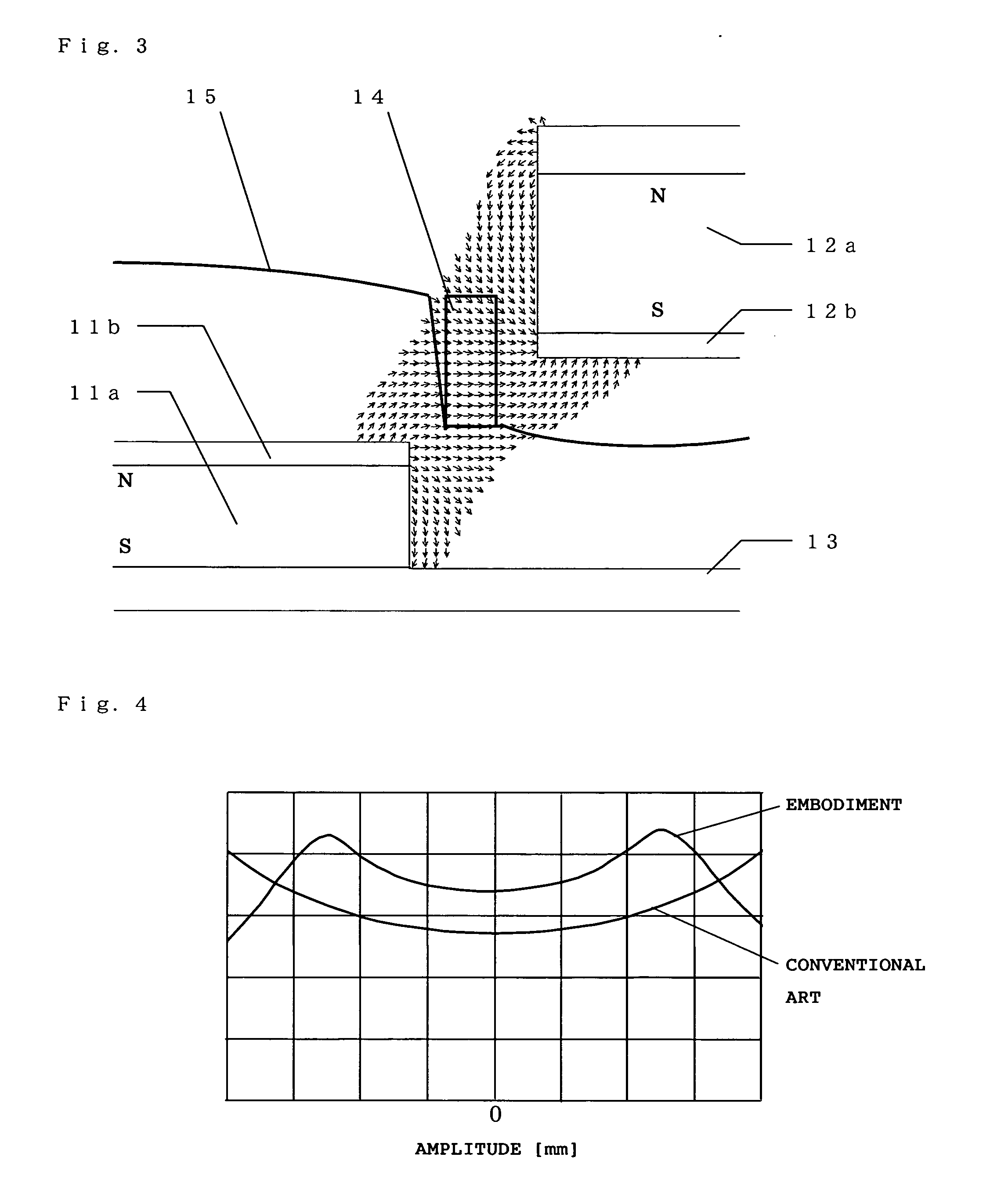
[0127] An electrodynamic electroacoustic transducer 1 according to a first embodiment of the present invention is described below with reference to FIGS. 1-4. Here, FIG. 1 is a structure sectional view of an electrodynamic electroacoustic transducer 1 according to a first embodiment. FIG. 2 is a perspective view where a part of the electrodynamic electroacoustic transducer 1 is cut off. FIGS. 3 and 4 are described later. In FIG. 1, the electrodynamic electroacoustic transducer 1 comprises a first magnetic pole 11, a second magnetic pole 12, a yoke 13, a voice coil 14, and a diaphragm 15. Here, as shown in FIG. 2, the shape of the electrodynamic electroacoustic transducer 1 viewed from vibrating directions is a circle. Further, the first magnetic pole 11 corresponds to the first magnetic pole part of the present invention, while the second magnetic pole 12 corresponds to the second magnetic pole part of the present invention.

[0128] The first magnetic pole 11 is constructed from a ma...

second embodiment

[0150] An electrodynamic electroacoustic transducer 2 according to a second embodiment of the present invention is described below with reference to FIGS. 12 and 13. Here, FIG. 12 is a structure sectional view of an electrodynamic electroacoustic transducer 2 according to the second embodiment. FIG. 13 is a perspective view where a part of the electrodynamic electroacoustic transducer 2 is cut off. In FIG. 12, the electrodynamic electroacoustic transducer 2 comprises a first magnetic pole 21, a second magnetic pole 22, a yoke 23, a voice coil 24, and a diaphragm 25. Here, as shown in FIG. 13, the shape of the electrodynamic electroacoustic transducer 2 viewed from the vibrating directions is a rectangle. Further, the first magnetic pole 21 corresponds to the first magnetic pole part of the present invention, while the second magnetic pole 22 corresponds to the second magnetic pole part of the present invention.

[0151] The first magnetic pole 21 is constructed from a magnet 21a and a...

third embodiment

[0160] An electrodynamic electroacoustic transducer 3 according to a third embodiment of the present invention is described below with reference to FIGS. 16 and 17. Here, FIG. 16 is a structure sectional view of an electrodynamic electroacoustic transducer 3 according to the third embodiment. FIG. 17 is a perspective view where a part of the electrodynamic electroacoustic transducer 3 is cut off. In FIG. 16, the electrodynamic electroacoustic transducer 3 comprises a first magnetic pole 31, a second magnetic pole 32, a yoke 33, a voice coil 34, and a diaphragm 35. Here, as shown in FIG. 17, the shape of the electrodynamic electroacoustic transducer 3 viewed from the vibrating directions is a shape like a racing track (referred to as a track shape, hereinafter) in which only the two opposing sides of the rectangle are formed by semicircles. Further, the first magnetic pole 31 corresponds to the first magnetic pole part of the present invention, while the second magnetic pole 32 corre...


PUM


Abstract

An electrodynamic electroacoustic transducer comprises: a first magnetic pole; a second magnetic pole that forms a magnetic gap between itself and the first magnetic pole and is arranged in a space excluding spaces in upper and lower face directions of the first magnetic pole; a yoke; a diaphragm; and a voice coil. The yoke magnetically couples one magnetic pole face of the first magnetic pole with one magnetic pole face of the second magnetic pole so as to support them. The diaphragm is arranged in a space in an upper face direction of the first magnetic pole and in a space in a lower face direction of the second magnetic pole, while its outer periphery is supported by the yoke. The voice coil is arranged in the magnetic gap and adhered to the diaphragm. At least one of the first magnetic pole part and the second magnetic pole part includes a magnet.

Description

TECHNICAL FIELD [0001] The present invention relates to an electrodynamic electroacoustic transducer and an electronic device and, in particular, to an electrodynamic electroacoustic transducer which is installed in an electronic device such as a portable telephone, a PDA (Personal degital assistant) a television receiver, a personal computer, a car navigation device, and a portable player and thereby reproduces an acoustic signal as well as to an electronic device in which the same is installed. BACKGROUND ART [0002] In the conventional art, in electronic devices such as portable telephones and PDAs, thickness reduction and power consumption reduction are advanced. In association with this, further size reduction and further efficiency improvement are desired also in electroacoustic transducers installed in these devices. The most general technique for improving the efficiency in an electroacoustic transducer is to increase the volume of the magnet. Nevertheless, the increase in th...

Claims


Application Information

Patent Timeline
Patent Type & Authority Applications(United States)
IPC IPC(8): H04R9/06
CPCH04R9/025H04R2499/11H04R2209/022
Inventor MATSUMURA, TOSHIYUKISAIKI, SHUJIKANO, SAWAKOSANO, KOJI
Owner PANASONIC CORP
Why Eureka
Try Eureka