Birefringent spectral filter with wide field of view and associated communications method and apparatus

a spectral filter and wide field of view technology, applied in the field of optical wavelength filters, can solve the problems of complication, more complicated geometry, and differential retardation, and achieve the effects of maximizing the bandpass amplitude, high transmission ratio, and maximizing the level of signal obtained

Active Publication Date: 2007-07-19
CHEMIMAGE TECH LLC
View PDF38 Cites 40 Cited by
  • Summary
  • Abstract
  • Description
  • Claims
  • Application Information

AI Technical Summary

Benefits of technology

[0015] An object of the present disclosure is to maintain a wide field of view in an optical receiver having a spectral filter, to accommodate reception of light on lines oblique to a center optical axis. The spectral filter has birefringent retarder plates wherein birefringence is affected by thickness, and obliquely propagating rays traverse a greater thickness than normal rays, tending to de-tune the filter with respect to oblique rays. A biaxial film is possible wherein the birefringence varies as a function of radial displacement from a center axis normal to the plates proceeding along the successive plates. Thus, in an arrangement wherein light is caused to diverge from a focal point, the light at progressively greater oblique angles radiating from the focal point can traverse portions of the retarder plates with a complementary variation in birefringence. It is an object to provide additional ways to provide a filter wherein the bandpass peak (or bandstop peak) remains acceptably nominal over the range of normal to oblique input angles in the field of view.

Problems solved by technology

Therefore, propagation through the birefringent material alters the polarization state of the light wave by causing differential retardation.
A complication arises if the light from a source is directed through the filter along paths that are not parallel to the center axis, i.e., propagating along lines that are oblique to a line that is normal to the planes of the retarders.
A more complicated geometry may be involved if the signal to be received is not oriented along a predetermined axis.
Conventional technology has limitations in high data rate communication between mobile platforms wherein a line of sight for a beam is not established.
Acoustic signaling is possible under water, but underwater conditions are unsuited to most forms of electromagnetic signaling, with the exception of very low frequency signals, which inherently are limited to a low data rate, and blue-green visible spectrum optical communications.
A line of sight would appear to be required, and if either or both of the sending and receiving ends are not fixed in position, the orientation of propagating beam can present issues at the receiver,
Although shading may help to reduce overhead sunlight, scattered sunlight remains a problem that is addressed.

Method used


Image

  • Birefringent spectral filter with wide field of view and associated communications method and apparatus
  • Birefringent spectral filter with wide field of view and associated communications method and apparatus
  • Birefringent spectral filter with wide field of view and associated communications method and apparatus

Examples


Embodiment Construction

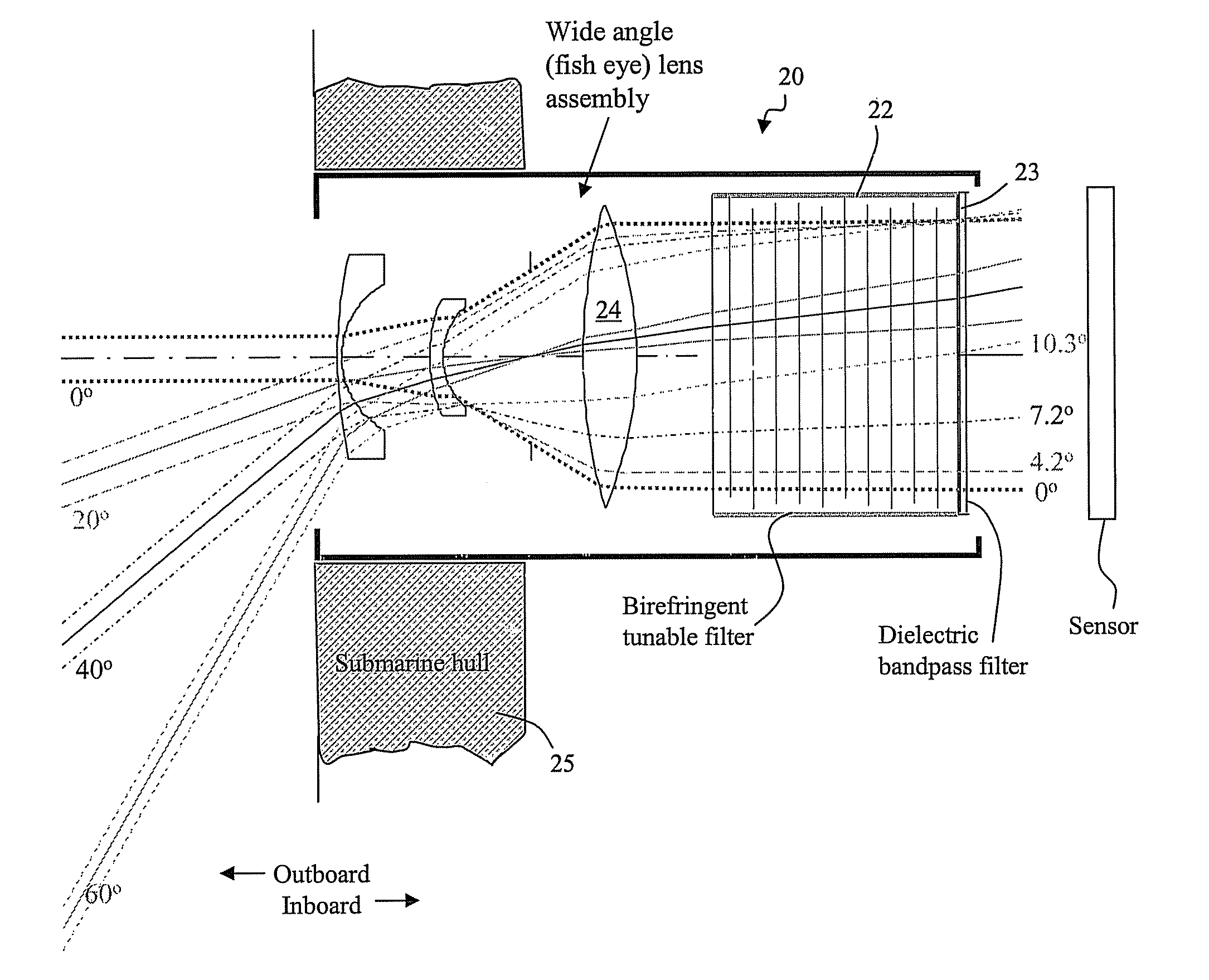
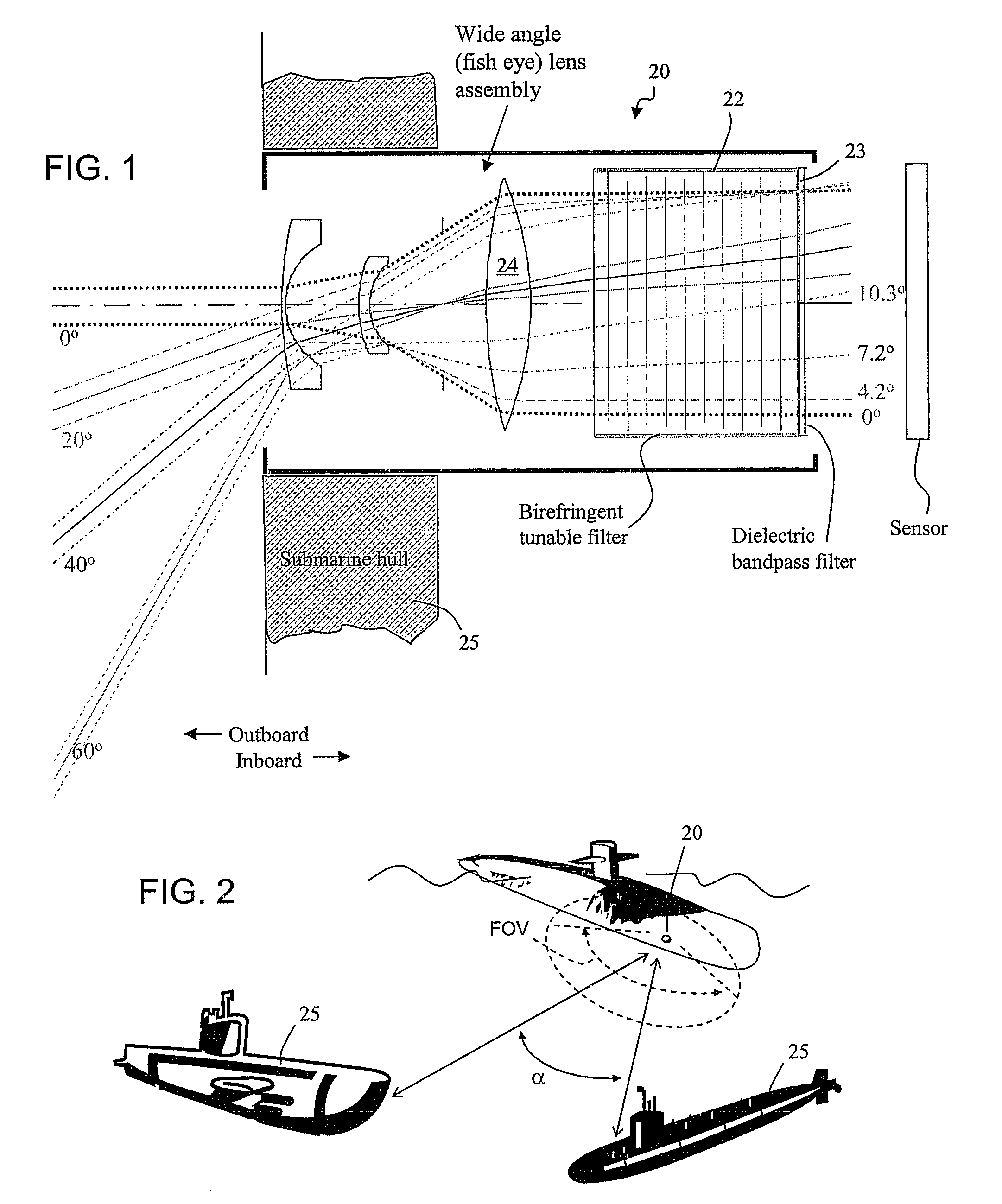
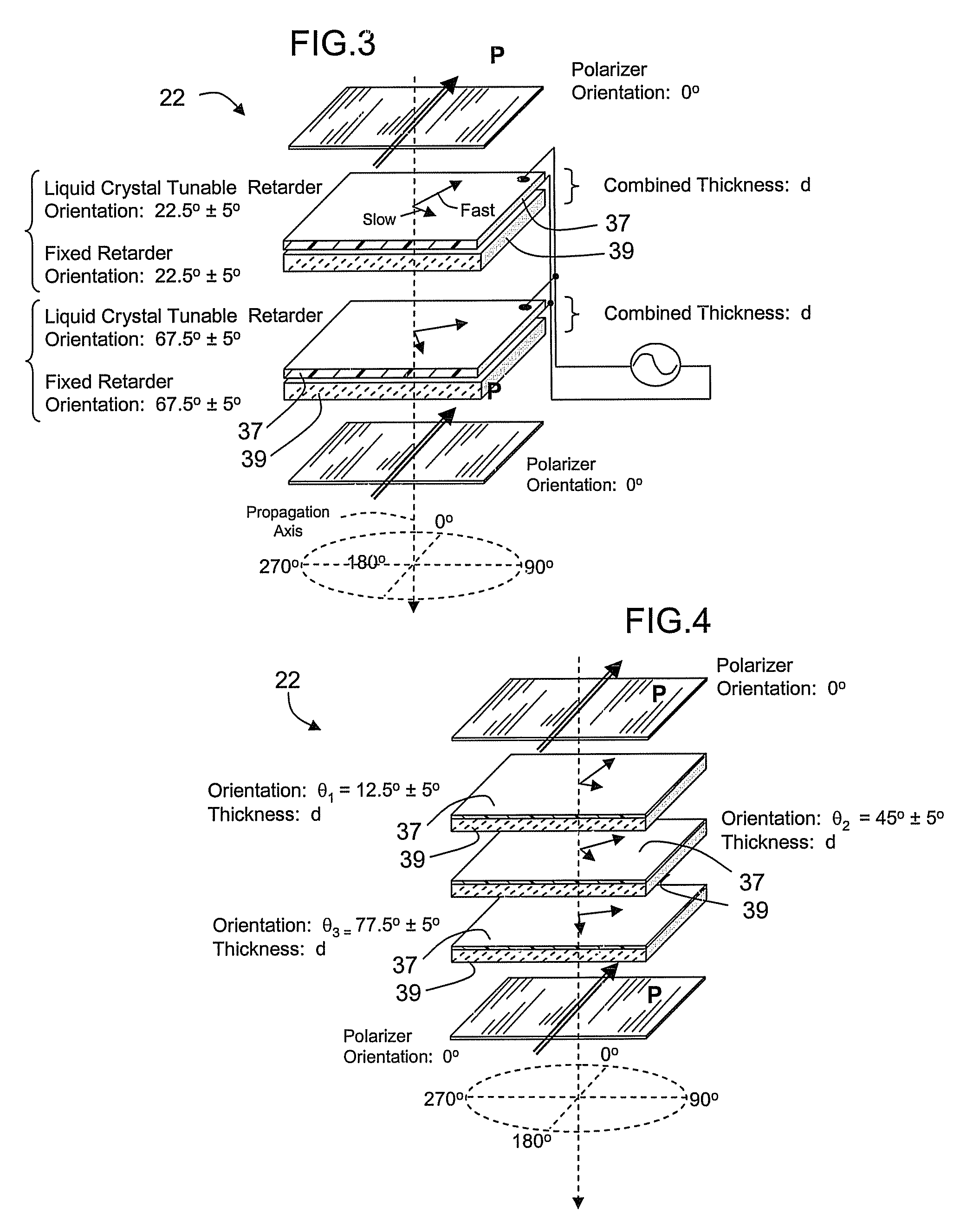
[0048] An optical receiver comprising a birefringence optical filter is disclosed herein, having a relatively wide field of view angle and a spectral filter apt for operation at short blue and green wavelengths, preferably capable of efficiently switching between operation at different short wavelengths. The spectral filter can comprise a set of birefringent differential retarder plates, preferably in cascaded stages. The retarders in a stage are arranged at particular rotational angles relative to one another and relative to at least one associated polarizer to produce a periodic comb filter transfer function. The transfer functions of stages in cascade are superimposed. In this respect, the subject matter can incorporate filter configuration aspects of U.S. Pat. No. 6,992,809 and pending application Ser. No. 11 / 537,233, filed Sep. 29, 2006, the disclosures of which are hereby incorporated into this description, in their entireties.

[0049] The disclosed receiver includes a spectral...


PUM


Abstract

A spectral filter is adapted for use in a receiver, for example in a short range submarine laser signal path, wherein the relative orientations of the receiver is such that the signal may appear diffusely or at an unknown point in a wide external field of view around an optical axis of the receiver. A narrow band spectral filter in the receiver has cascaded stages of tunable retarders with includes multi-conjugate stages that tolerate light that is oblique to normal, up to a diverging internal field of view angle up to about 10°. A fisheye lens assembly refracts incoming light from a wider external field of 170° or more and directs the light into the filter over the narrow internal field of view. Calibration and feedback control can be provided to stabilize the discriminated wavelength peak, which remains at the same center wavelength over the span of the internal field of view notwithstanding the difference in retarder thicknesses traversed along paths that are normal to the retarders versus oblique to the optical axis.

Description

CROSS REFERENCE TO RELATED APPLICATION [0001] This application claims priority of U.S. Provisional Application 60 / 757,268, filed Jan. 9, 2006.BACKGROUND [0002] This disclosure concerns optical wavelength filters for narrow bandwidth discrimination. An optical receiver is provided with a receiving lens assembly coupled to a birefringence and polarization optical wavelength filter having stacked retarders configured for tolerance to obliquely propagating light. The receiver is apt for a laser receiver operating in a diffuse medium, such as a short range undersea optical receiver responsive to modulated blue-green short wavelength laser communications. The receiver also is applicable to situations wherein a direct line of sight from the source to the receiver is uncertain and can be oblique to the optical signal path at the receiver. [0003] A tunable multi-conjugate birefringence wavelength filter is disclosed in U.S. Pat. No. 6,992,809, which is incorporated in this disclosure in its ...

Claims


Application Information

Patent Timeline
Patent Type & Authority Applications(United States)
IPC IPC(8): H04B10/00
CPCG02B27/283G02F1/13318G02F1/133526G02F1/13363G02F2203/18G02F1/13473G02F1/21G02F2202/40G02F2203/01G02F1/1347
Inventor WANG, XINGHUA
Owner CHEMIMAGE TECH LLC
Why Eureka
Try Eureka