Endovascular method and apparatus with electrical feedback

a technology of endovascular and electrical feedback, applied in the field of endovascular apparatus with electrical feedback, can solve the problems of overheating and burnback of cladding and other buffer materials on the fiber tip, weakened fiber integrity, and continued lamination, so as to prevent burn back

Inactive Publication Date: 2007-07-19
BROWN JOE DENTON
View PDF8 Cites 35 Cited by
  • Summary
  • Abstract
  • Description
  • Claims
  • Application Information

AI Technical Summary

Benefits of technology

[0013] It is accordingly a first objective of the invention to provide an apparatus for delivery of energy to a tissue within a patient, in which damage to the energy delivery device is minimized by preventing contamination of the device by bodily fluids that might cause overheating and / or burning of tissues, bodily fluids, or the apparatus itself.
[0014] It is a second objective of the invention to provide apparatus for monitoring a surgical procedure involving delivery of energy to tissues in a body cavity, in which overheating can be rapidly and reliably detected with our without the addition of a black body emitter and at any wavelength indicative of such overheating, including visible wavelengths, before or after a pyrolytic glow occurs. It is a third objective of the invention to provide a vascular treatment apparatus and method that prevents blood contamination and burn back, and that can be reliably monitored through an introducer and / or a cladding of a laser delivery fiber.
[0015] These objectives are accomplished by modifying the conventional fiber introducer so as to prevent any blood left in the catheter after preparation of the vein for treatment from contacting the fiber tip. The fiber introducer may either be modified to enclose the fiber, in which case laser light is transmitted through the introducer to the treatment area, or the fiber introducer may be arranged such that a liquid in the introducer, for example a saline solution, will flush blood away from the fiber tip. To help prevent contaminants from sticking to the introducer, the introducer is preferably be made of a low friction material such as Teflon, which also has the advantage of permitting smooth drawback of the laser deliver device inside the vein without sticking to tissue or blood.
[0017] If the introducer is completely closed off at the distal end, the introducer may advantageously include a highly flexible or floppy tip and / or may be rounded off to eliminate the need for a guide wire, saline flush, and hemostasis valve. Alternatively, the sheath may be provided at the distal end with a reduction means or septum to prevent or minimize blood from entering the catheter, but still allow for a guide wire to pass through the introducer sheath and the reduced end or septum. In that case, means for introducing saline may also be allowed to clean the catheter internal diameter from blood residue.
[0020] The detector of the preferred embodiments may of course be used with apparatus that include an introducer of the type described above, as well as with conventional apparatus in which the fiber tip is exposed. In case the fiber tip is exposed, a heat sink or shield may still be added to help prevent burn back.

Problems solved by technology

While this treatment arrangement is effective in treating varicose veins, a problem with the treatment method is that, as the length of the vessel being treated increases, contact between the fiber tip 4 and blood 5 in the vein can cause overheating and burn back of cladding and other buffer materials on the fiber tip, as illustrated in FIGS. 2A and 2B.
In addition to damaging the fiber cladding, burn back can cause continued lasing, charring or carbonization, and weakened fiber integrity.
For example, exposing the silica core of a fiber can allow carbonization to the sides of the fiber tip making it weak with the possibility of falling off into the vein.
Furthermore, carbonization forming on the distal tip can locally heat the distal fiber tip surface to extreme temperatures sufficient to enough to cause the fiber to start absorbing infrared radiation, thereby causing a thermal runaway that could perforate the vein wall.
Still further, charring and / or other effects of overheating or thermal runaway can directly cause negative effects on the patient, such as operative or post-operative pain and / or toxic reactions to compounds resulting from burning or vaporization of materials such as Teflon™.
Finally, if the burn back exposes the surfaces on the side of the fiber, then energy is stolen from the core, making the power density lower and effecting the treatment.
Despite these problems, however, little has been done to prevent burn back, with the primary focus being to monitor the procedure and replace the fiber or clean the fiber tip before significant burn back occurs.
However, fibers with modified tips typically build up char and burn up or have break off failures and therefore this solution is not practical.
Unfortunately for the patient, by the time that pyrolytic glow or black body radiation is observed, substantial burn back, vein char or perforation may already have occurred.
In addition, the inclusion of a separate black body emitter, as disclosed in U.S. Pat. No. 6,932,809, is both inconvenient and expensive.

Method used


Image

  • Endovascular method and apparatus with electrical feedback
  • Endovascular method and apparatus with electrical feedback
  • Endovascular method and apparatus with electrical feedback

Examples


Embodiment Construction

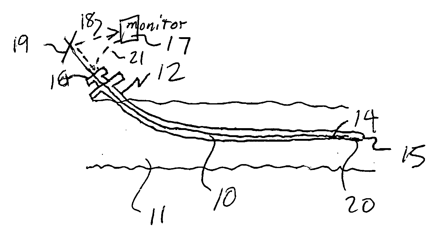
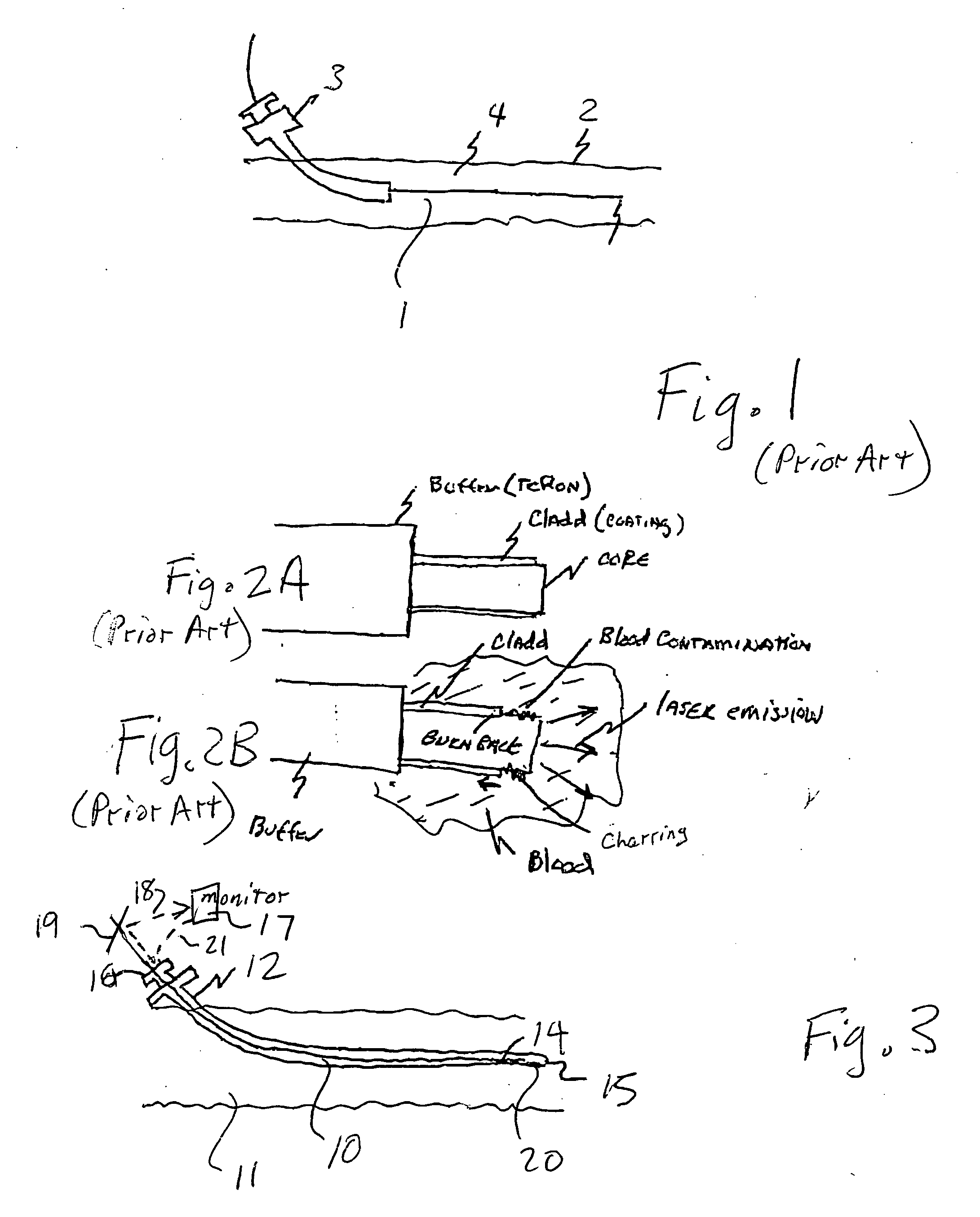
[0027] As illustrated in FIG. 3, the apparatus of a preferred embodiment of the invention includes an energy delivery device in the form of an optical fiber 10 that is introduced into the vessel 11 by means of a Teflon_ introducer 12. The Teflon introducer lacks a homeostasis valve and has a closed end 13 that extends beyond the tip 14 of the fiber 10 and that has an end 15 arranged to prevent contamination of the fiber tip 14 by blood 11 in the vessel. The Teflon introducer may optionally include a motorized fiber pull back 16. In addition, a detector 17 may be included, as described in more detail below.

[0028] End 15 of the introducer may be either open or closed. If it is completely closed, then the end may including cooling means within the introducer for cooling the fiber. Cooling means for use in a catheter are well known and the details of the cooling means do not form a part of the present invention. Alternatively, the end 15 of the introducer may be open, in which case sal...


PUM


Abstract

An apparatus for delivering energy, and in particular laser energy, to a tissue is adapted to minimize or eliminate burn back caused by contact between the energy delivery apparatus and bodily fluids by (i) preventing the energy delivery apparatus from contacting bodily fluids or tissues that might burn or cause the apparatus to burn; and / or (ii) monitoring the apparatus to detect overheating in order to withdraw the apparatus or control the energy supply in case overheating is detected. The apparatus is applicable, by way of example, to treatment of blood vessels using endovascular techniques.

Description

[0001] This application is a continuation-in-part of U.S. patent application Ser. No. 11 / 510,691, filed Aug. 28, 2006, which claimed the benefit of U.S. Provisional Application Ser. Nos. 60 / 711,273, filed Aug. 26, 2005.BACKGROUND OF THE INVENTION [0002] 1. Field of the Invention [0003] This invention relates to apparatus for delivering energy to a tissue, and in particular to apparatus for minimizing damage caused by overheating of either the tissue or the energy delivery apparatus by: (i) preventing the energy delivery apparatus from contacting bodily fluids or tissues that might burn or cause the apparatus to burn; and (ii) monitoring the apparatus to detect overheating in order to withdraw the apparatus or control the energy supply in case overheating is detected. [0004] The apparatus of the invention is applicable, by way of example, to treatment of blood vessels using endovascular techniques for delivering laser energy. The apparatus is arranged to prevent an optical fiber from...

Claims


Application Information

Patent Timeline
Patent Type & Authority Applications(United States)
IPC IPC(8): A61B18/18
CPCA61B18/20A61B2018/00636A61B18/24
Inventor BROWN, JOE DENTON
Owner BROWN JOE DENTON
Why Eureka
Try Eureka