
Surgical tool holder for facilitated sterilization

a technology of surgical tools and sterilization, applied in the field of surgical tools, can solve the problems of increasing the risk of disease transmission from patient to patient, difficult to use current solutions without subjecting the patient, and difficult to clean, etc., to facilitate sterilization, facilitate sterilization, and prevent the separation of component parts

Active Publication Date: 2007-07-19
VIANT AS&O HLDG LLC
View PDF32 Cites 59 Cited by
  • Summary
  • Abstract
  • Description
  • Claims
  • Application Information

AI Technical Summary

Benefits of technology

"The present invention is a surgical tool holder that allows for easy sterilization and cleaning. It has a break-away feature that allows for partial disassembly without separating component parts. The holder ensures easy orientation of the surgical tool or other device attached to its interface. It also prevents the separation of component parts from the device as a whole. The holder enables firm locking against rotation or rocking of the attached tool or prosthesis. Overall, the invention provides a tool holder that is easy to use, sterilize, and securely locks the attached tool or prosthesis."

Problems solved by technology

Complicated mechanical devices have crevices and recesses that are difficult, if not almost impossible to clean with ease without disassembly into separate component parts.
Devices that are not properly cleaned and sterilized increase the risk of disease transfer from patient to patient.
Further, in surgical procedures in which access to the treatment site is limited, it is difficult to use current solutions without subjecting the patient to repeated abrasion and tissue trauma when inserting and extracting surgical instruments.
Additionally, the insertion of a prosthetic implant is often problematic, and the orientation of the implant in a properly prepared recess is often critical to minimize recovery time of the patient.
Still further, once the appropriate position of the tool is selected, it is often difficult to ensure that the position does not change upon insertion of the assembly through the incision.

Method used


Image

  • Surgical tool holder for facilitated sterilization
  • Surgical tool holder for facilitated sterilization
  • Surgical tool holder for facilitated sterilization

Examples


Embodiment Construction

)

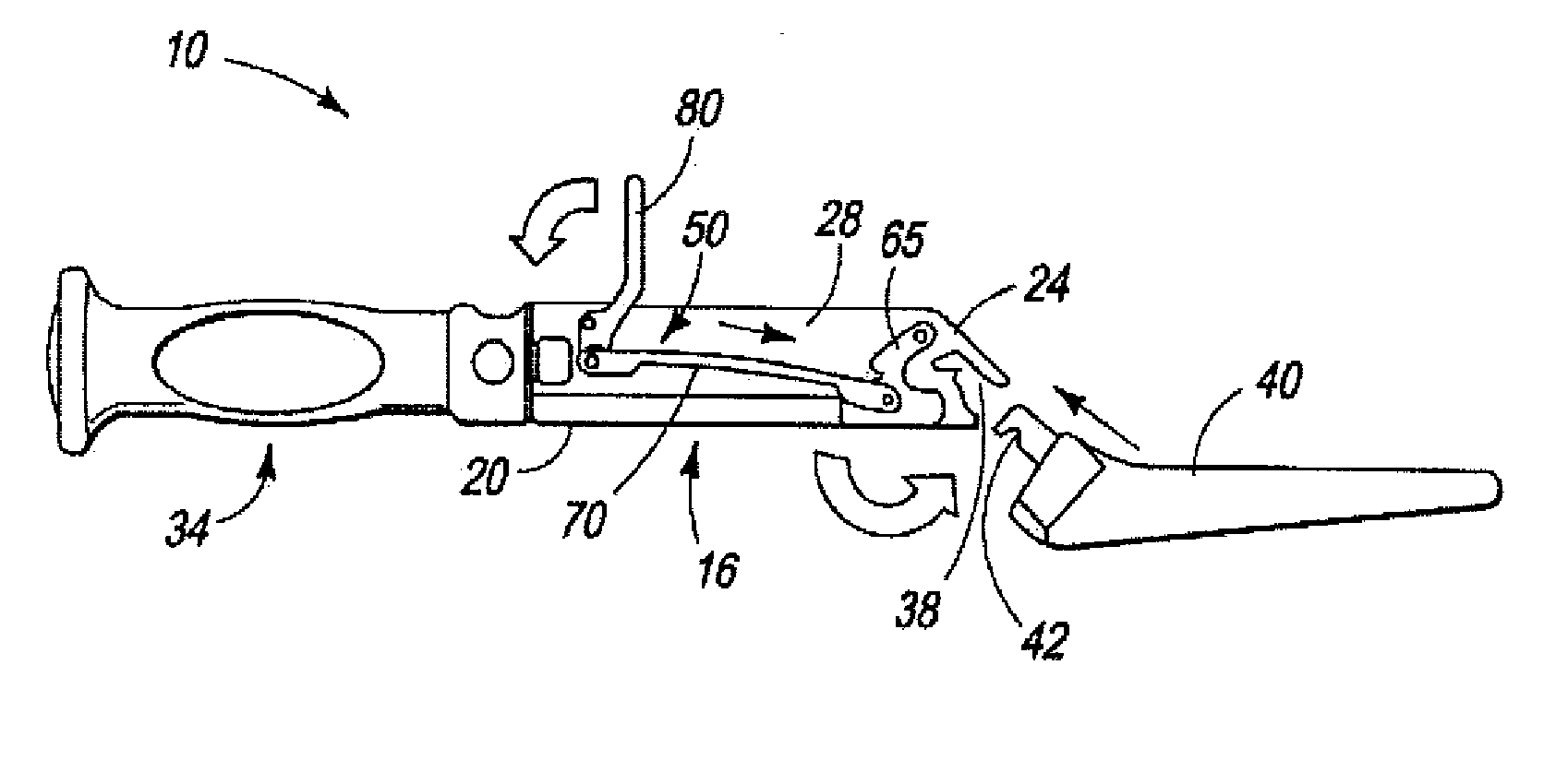
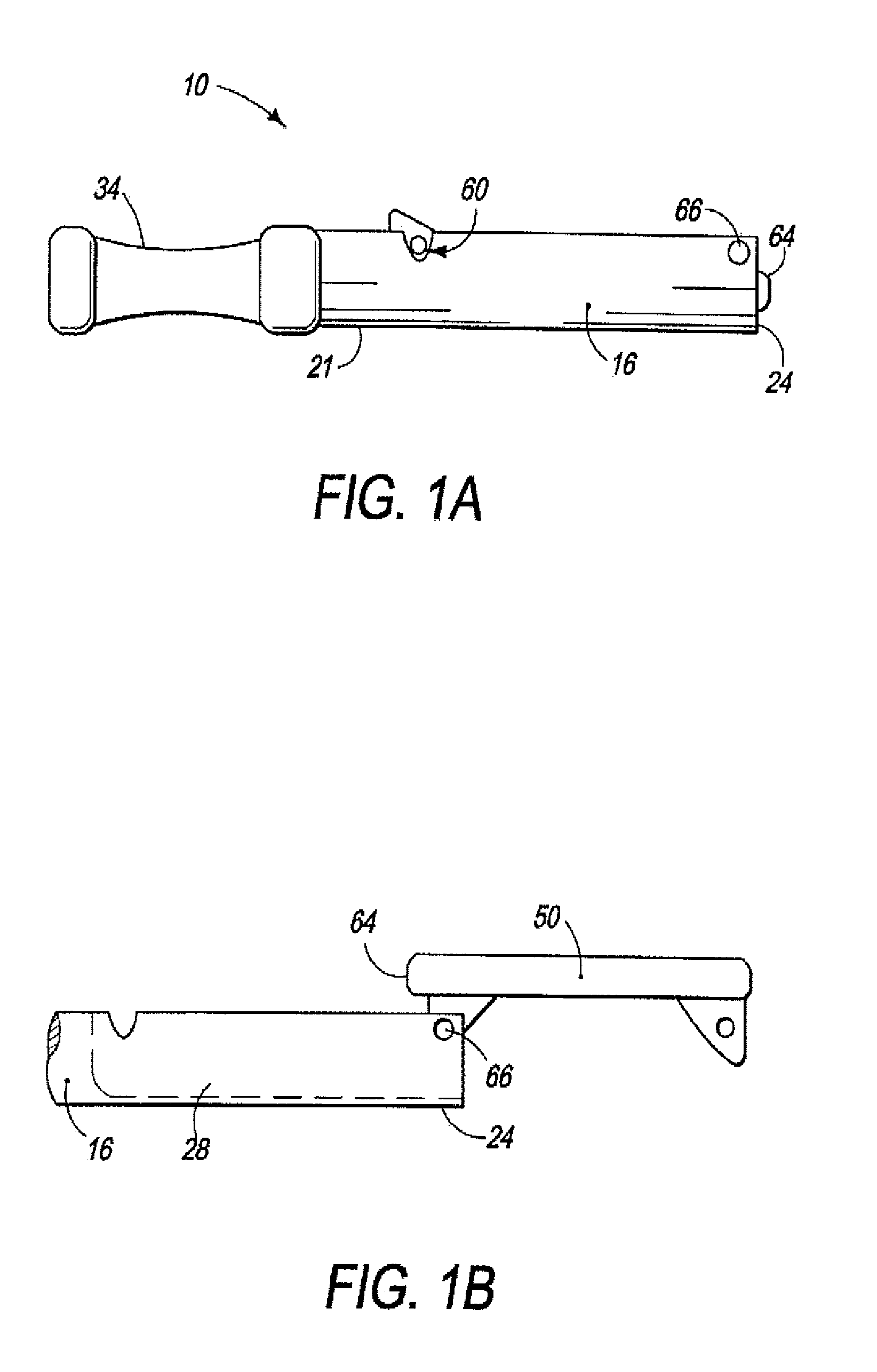
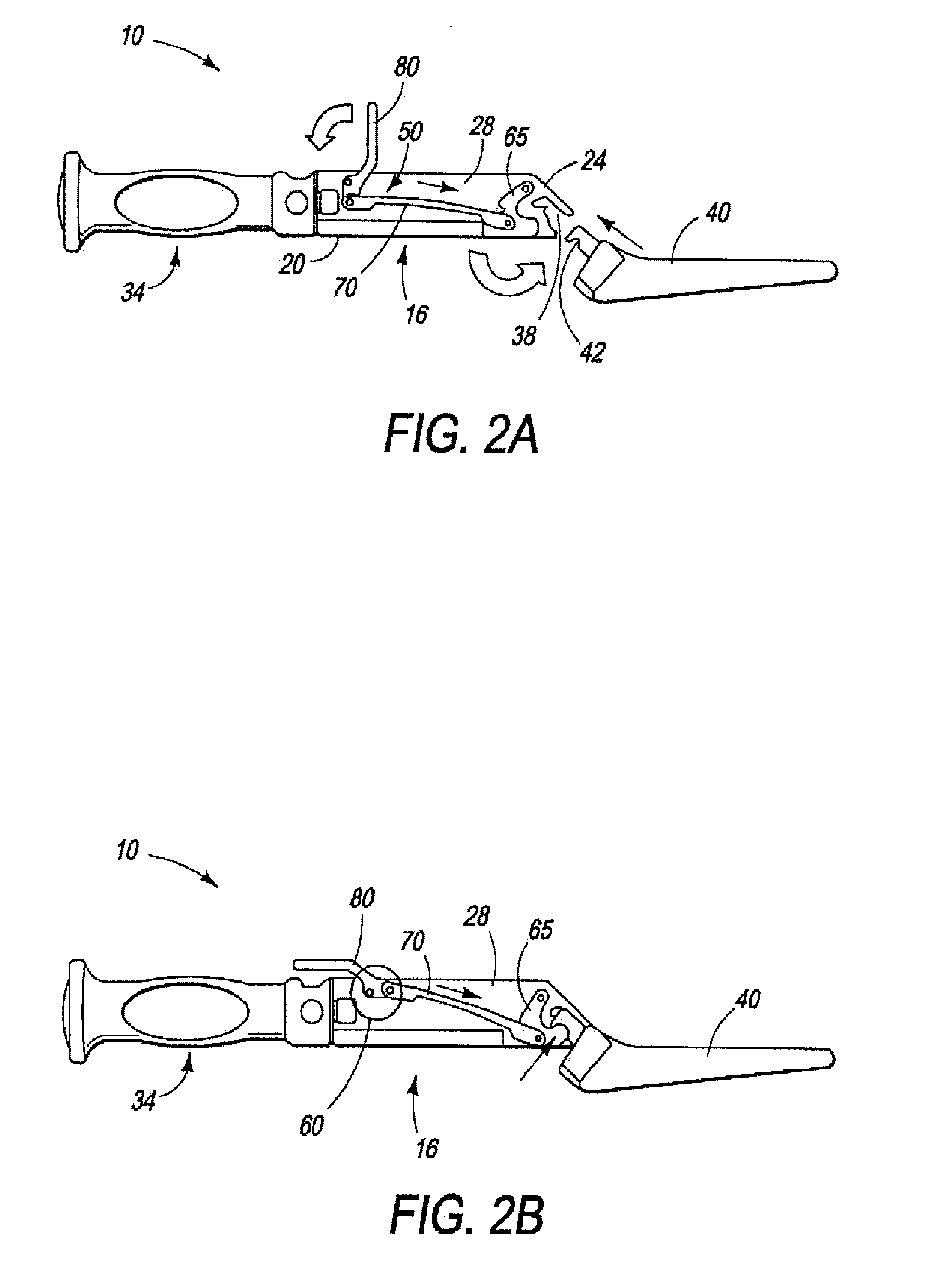
[0032] The present invention is a surgical tool holder configured for facilitated cleaning and sterilization. Various surgical / orthopedic tool heads useful for surgical procedures can be mounted on the tool holder. The present surgical tool holder includes a tool holder linkage having an interface for attaching a tool head to the holder. The tool holder linkage is partially removable from the body of the surgical tool holder to facilitate cleaning and sterilization of the device as a whole. The tool holder linkage intentionally is only partially removable from the body of the handle to prevent its component parts from being separated the device as a whole, for example during cleaning, handling or storage, and so as to avoid the parts subsequently becoming lost or misplaced. Various surgical / orthopedic tool heads useful for surgical procedures can be mounted on the tool holder.

[0033] An objective of the present invention is to be easily cleaned and sterilized. This is accomplished ...


PUM


Abstract

A surgical tool holder aids a surgeon in controlling the use of a tool during, for example, preparation of a femoral cavity for reception of hip joint prosthesis. The holder has a housing that encloses a mechanism having, at a far end, a tool-engaging interface, and at the opposite end, a handle which facilitates manipulation of the tool during use in preparing a bone site by the surgeon. The holder enables easy orientation of the tool attached to its end, which is important because control of the tool is critical in order to accurately prepare a recess for reception and installation of a prosthesis.

Description

CROSS-REFERENCE TO RELATED APPLICATIONS [0001] The present application claims priority to previously filed U.S. Patent Application Ser. No. 60 / 783,900, filed Mar. 20, 2006 and PCT Patent Application Serial Number PCT / IB2005 / 003720, filed Dec. 30, 2005, and includes by reference the contents thereof.FIELD OF THE INVENTION [0002] This invention relates to surgical tools for aiding in the installation of orthopedic prostheses in patients. More particularly, the present invention relates to easily sterilizable holders for use with a surgical tool in preparing a bone site, and for use in installing a prosthesis in the bone. BACKGROUND OF THE INVENTION [0003] Complicated mechanical devices have crevices and recesses that are difficult, if not almost impossible to clean with ease without disassembly into separate component parts. Devices that are not properly cleaned and sterilized increase the risk of disease transfer from patient to patient. This is especially true following the emergenc...

Claims


Application Information

Patent Timeline
Patent Type & Authority Applications(United States)
IPC IPC(8): A61F2/00
CPCA61B17/162A61B17/1659A61B17/1666A61B2017/0046A61B2019/4868A61F2/4607Y10T74/20738A61F2002/30476A61F2002/3404A61F2002/4623A61F2002/4629A61F2220/0025A61F2/4609A61B2090/0813A61F2/4603A61F2002/3403
Inventor BURGI, JONASLECHOT, ANDRE
Owner VIANT AS&O HLDG LLC
Learn More