Electric hybrid vehicle conversion

a hybrid vehicle and electric motor technology, applied in the direction of engine-driven generators, battery/cell propulsion, transportation and packaging, etc., can solve the problems of insufficient torque output of ic engine, inordinately large initial cost, heavy and expensive electric motors, etc., and achieve the effect of minimal cost and effor

Inactive Publication Date: 2007-07-26
KYDD PAUL HARRIMAN
View PDF5 Cites 95 Cited by
  • Summary
  • Abstract
  • Description
  • Claims
  • Application Information

AI Technical Summary

Benefits of technology

[0021]It is a further object of this invention to make it easy to convert a conventional automobile or truck to a hybrid configuration with minimal changes and few additional parts of standard design and ready availability.
[0022]The invention enables the provision of retrofit kits and instructions which can be used to convert existing or new vehicles to parallel plug hybrid operation with minimal cost and effort.

Problems solved by technology

However, the patent envisions only a mild hybrid capability with a small 15 kW electric motor.
Previous proposed attempts to provide conversion kits to create hybrid vehicles required specially designed electric motors, which increases initial cost substantially and requires an inventory of different motor types to convert different IC vehicles.
The direct incorporation of the electric motor in the drive train in previous proposals either restricts the torque and power supplied electrically to a minimal augmentation of the IC engine or requires an inordinately large, heavy and expensive electric motor to match the torque output of the IC engine.

Method used


Image

  • Electric hybrid vehicle conversion
  • Electric hybrid vehicle conversion
  • Electric hybrid vehicle conversion

Examples


Embodiment Construction

—THE PREFERRED EMBODIMENT

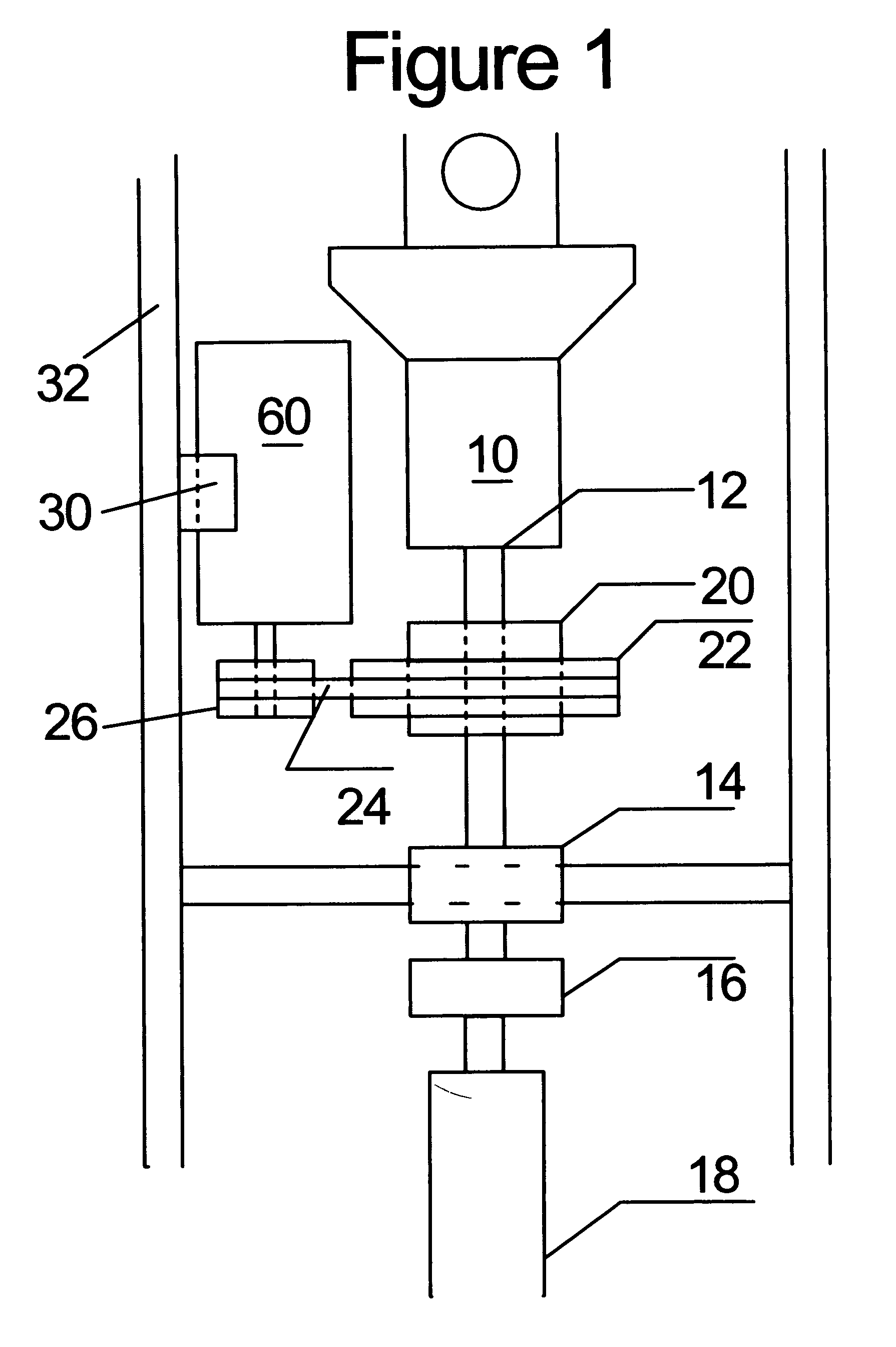
[0026]FIG. 1 schematically illustrates the mechanical components of the hybrid drive system in which an internal combustion engine transmission 10 has an output shaft 12 which is supported by pillow block 14. The drive shaft drives propeller shaft 18 through universal joint 16 to propel the vehicle.

[0027]The added mechanical components of the hybrid system include clutch 20, mounted on and attached to output shaft 12 by a keyway or spline. For example, the outer diameter of the universal joint yoke engaging the splined end of output shaft 12 may be turned down and provided with a keyway to engage clutch 20. Clutch 20, may be of the roller ramp or cam type of overrunning clutch allowing relative motion in one direction but locking to the shaft in the other direction, for example the FormspragFSO-550 clutch from Warmer Electric, Warren, Mich. The clutch is driven by a flexible speed reduction subsystem consisting of pulley 22, timing belt 24 and pulley 26. It ...


PUM


Abstract

An assembly is described for converting an Internal Combustion (IC) vehicle to an IC-electric hybrid vehicle comprising a battery, a battery charger, a controller, an electric motor and a power transmission means involving a flexible rotational speed reduction to connect the motor to a drive shaft of the vehicle. The system can be made available in the form of a kit allowing those skilled in automobile mechanics to perform the conversion. Regenerative braking and provision of AC power from the vehicle can be made available as options.

Description

CROSS-REFERENCE TO RELATED APPLICATIONS[0001]This application claims the benefit of U.S. Provisional Patent Application Ser. No. 60 / 761,231 filed Jan. 23, 2006, the complete disclosure of which is hereby expressly incorporated by reference.CITED LITERATURE[0002]Reed, et al, U.S. Pat. No. 6,332,257, Dec. 25, 2001[0003]Gilmore, C. D., U.S. patent application No. 2005 / 0205313, Sep. 22, 2005[0004]Hughey; Charles E. U.S. patent application No. 2006 / 0000650, Jan. 5, 2006 “The Electric Car” Michael H. Westbrook, Institution of Electrical Engineers, Stevenage, UK / SAE Warrendale, Pa., 2001[0005]EPRI Portfolio 2006, P018-001 through -004[0006]Kempton, W.; Tomic, J.; Letendre, S.; Brooks, A.; Lipman, T. Vehicle-to-Grid Power: Battery, Hybrid and Fuel Cell Vehicles as Resources for Distributed Electric Power in California, udel.edu / V2G, University of Delaware, 2001[0007]AC Propulsion inc. acpropulsion.com / Veh_Grid_Power / Veh_grid_power.htmFEDERALLY SPONSORED RESEARCH[0008]NoneBACKGROUND OF THE I...

Claims


Application Information

Patent Timeline
Patent Type & Authority Applications(United States)
IPC IPC(8): B60K6/00B60K6/48
CPCY02T10/6221B60K6/48B60L2270/40Y02T10/70B60L50/16B60L50/51Y02T10/62Y02T10/7072
Inventor KYDD, PAUL H.
Owner KYDD PAUL HARRIMAN
Why Eureka
Try Eureka