Eureka AIR delivers breakthrough ideas for toughest innovation challenges, trusted by R&D personnel around the world.

Suspension apparatus for a wheeled vehicle utilizing offset frame with torsion shock absorber

Inactive Publication Date: 2007-07-26
PATMONT MOTOR WERKS
View PDF33 Cites 9 Cited by
  • Summary
  • Abstract
  • Description
  • Claims
  • Application Information

AI Technical Summary

Benefits of technology

[0015] A wheeled vehicle includes a front steered wheel, a rear driven wheel, and a support member that supports a rider. A main structural tube is disposed substantially horizontally along a longitudinal axis for supporting the front steered wheel at a forward end of the main structural tube, for supporting the rear driven wheel at the rear end of the main structural tube, and for supporting a rider who controls and steers the wheeled vehicle. An improved torsion acting shock absorbing mount is disclosed for the cantilevered shock absorbing support of at least one of the vehicle wheels from the frame. The torsion acting shock absorber includes a square sectioned metal tube, a correspondingly square sectioned metal shaft, and confined compressible rubber rods acting there between. As used herein, rubber rods or bars or other equivalent resilient substances such as natural or synthetic rubber-like substances may be used. The torsion acting shock absorber is attached at right angles to the main structural tube and protrudes at an end to one side of the main structural tube. A cantilevered wheel support is mounted offset from the main structural tube at the end of the shock absorber remote from the main structural tube. The square tube fastens at right angles to the main structural tube while the square metal shaft connects to the cantilevered wheel support. The cantilevered wheel support torsion rotates through the shock absorber at right angles with respect to the main structural tube to undertake shock absorbing movement between at least one of the wheels and the main structural tube, and the rider. Provision is made for applying the shock absorber between the cantilevered driving wheel, the cantilevered steering wheel, or both. The economical manufacture of the wheeled vehicle with cantilevered wheel mounting is enabled together with protected mounting of the torsion acting shock absorber during vehicle operation.
[0016] An advantage of this invention is that the shock absorber naturally disposes the cantilevered wheel mount away from the main structural tube. By the expedient of cantilevering the wheel from the cantilevered wheel mount back into alignment with the axis of the main structural tube, an economically constructed and wheel aligned motorized vehicle results.
[0017] A further advantage of this invention is that the torsion acting shock absorber is completely self-contained and protected from the elements.

Problems solved by technology

Further, the feet of the rider can be knocked out of position on the platform or the feet of the rider can damage the shock absorber.
Where the shock absorber is mounted below the platform, the shock absorber is inevitably exposed to the underlying irregular terrain.
Where the shock absorber is exposed to the underlying irregular terrain, the inevitable particulate matter impacting the shock absorber can interfere with shock absorber operation and even damage the shock absorber to the point of inoperability.
When the trailer encounters shock inducing bumps along its path of travel, shock absorbing movement of the crank mounted wheel occurs.
Second, for the functioning of the scooter, it is required that the shock absorber be confined in a completely protected manner while at the same time functioning to dampen the inevitable shock which the scooter undergoes during use.

Method used


Image

  • Suspension apparatus for a wheeled vehicle utilizing offset frame with torsion shock absorber
  • Suspension apparatus for a wheeled vehicle utilizing offset frame with torsion shock absorber
  • Suspension apparatus for a wheeled vehicle utilizing offset frame with torsion shock absorber

Examples


Embodiment Construction

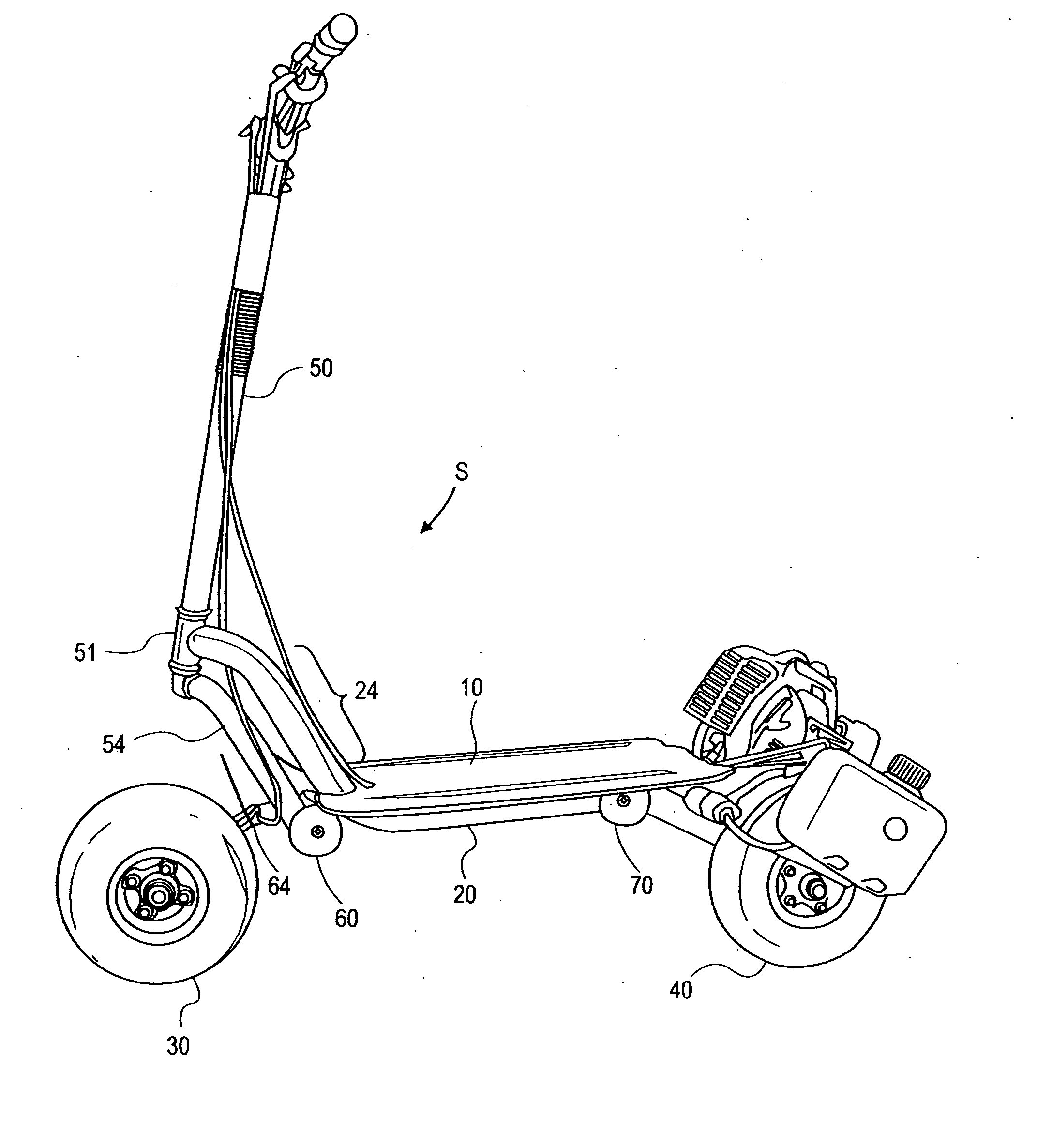
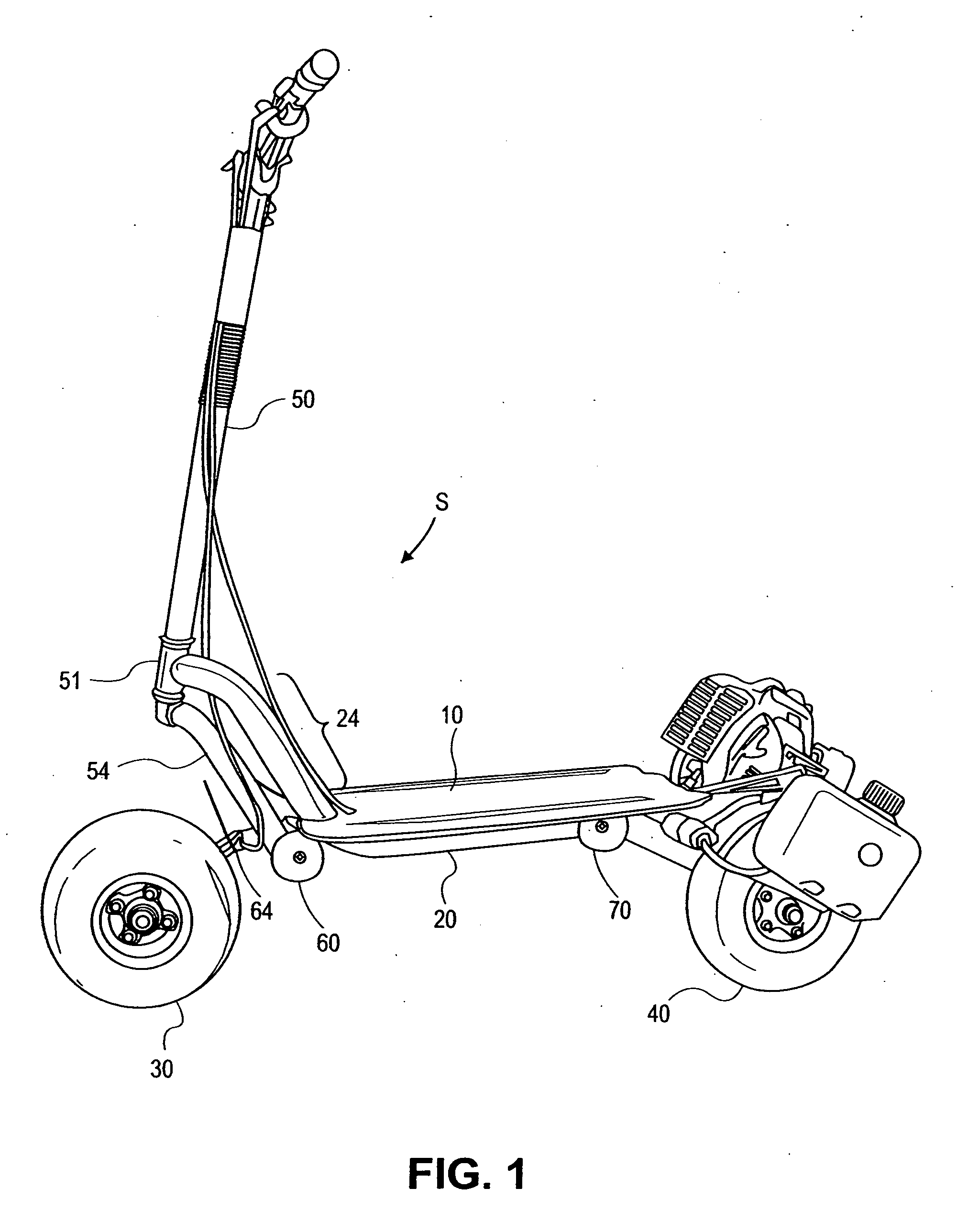
[0033] Referring to FIG. 1, scooter S is shown having platform 10, main structural tube 20, front steered wheel 30, rear driven wheel 40 and upwardly extending steering handle 50. Simply stated, a rider stands on platform 10, steers steering handle 50, and operates throttle and brake controls mounted to handle 50 for scooter operation. In the view here shown, first torsion shock absorber 60 mounts steered wheel 30 to steering handle 50 and main structural tube 20 while a second torsion shock absorber 70 mounts motor driven wheel 40 to main structural tube 20.

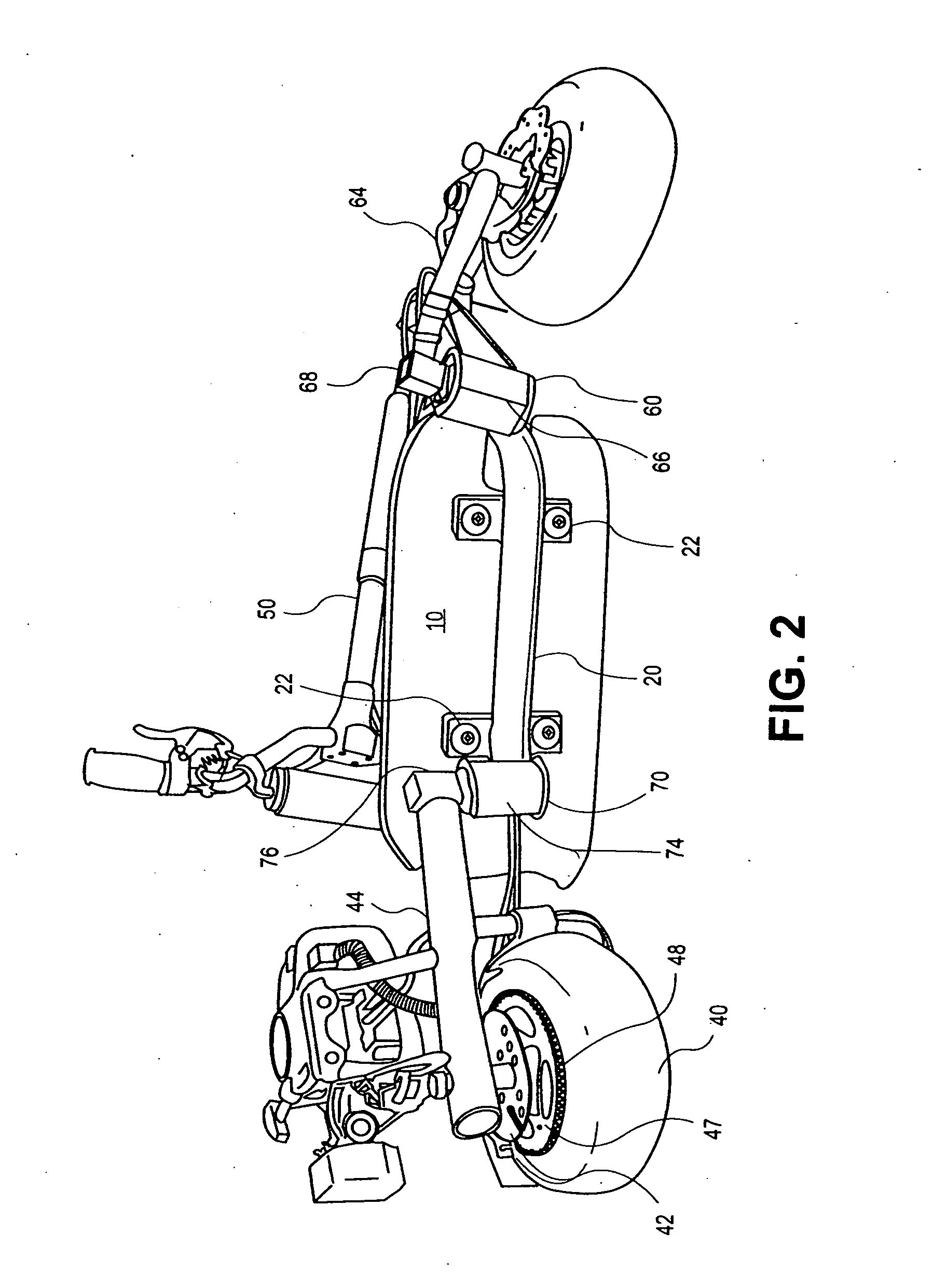
[0034] Having set forth the main elements of this invention, attention can be devoted to the bottom perspective view illustrated in FIG. 2 which conveniently illustrates the difference between the suspension system applied to the front steered wheel 30 and the rear driven wheel 40. First, main structural tube 20 supports platform 10 at respective screw pads 22. As shown in FIG. 1, structural tube 20 bends arcuately upward at ar...


PUM


Abstract

A wheeled vehicle includes a front steered wheel, a rear driven wheel, and a support member that supports a rider. A main structural tube is disposed substantially horizontally along a longitudinal axis for supporting the front steered wheel at a forward end of the main structural tube, for supporting the rear driven wheel at a rear end of the main structural tube, and for supporting a rider who controls and steers the wheeled vehicle. An improved torsion acting shock absorbing mount is disclosed for the cantilevered shock absorbing support of at least one of the vehicle wheels from the frame. The torsion acting shock absorber includes a square sectioned metal tube, a correspondingly square sectioned metal shaft, and confined compressible resilient compound rods acting there between. The torsion acting shock absorber is attached at right angles to the main structural tube. A cantilevered wheel support is mounted offset from the main structural tube at the end of the shock absorber remote from the main structural tube. The square tube fastens at right angles to the main structural tube while the square metal shaft connects to the cantilevered wheel support. The cantilevered wheel support torsion rotates through the shock absorber at right angles with respect to the main structural tube to undertake shock absorbing movement between at least one of the wheels and the main structural tube, and the rider.

Description

CROSS-REFERENCE TO RELATED APPLICATION [0001] This application is a continuation-in-part of application Ser. No. 11 / 082,211, filed Mar. 15, 2005, the disclosure of which is hereby incorporated by reference.[0002] This invention relates to wheeled vehicles. More particularly, this invention relates to a vehicle suspension adaptable to so-called offset frames where torsion shock absorbers provide both the required frame offset from which cantilevered wheels can be mounted and from which shock absorbing movement of one part of the vehicle frame relative to another part of the vehicle frame can occur. BACKGROUND OF THE INVENTION [0003] All-terrain scooters are known. See Patmont, U.S. Pat. No. 6,012,539. The “all-terrain” scooter disclosed therein is provided with a large central tubular chassis having two central brackets supporting a platform. At the front, the tubular chassis bends upward through a notch in the platform upwardly and above the front wheel to support a steering wheel h...

Claims


Application Information

Patent Timeline
IPC IPC(8): B60G21/055B62K3/00B62K11/10B62K25/00B62K25/16B62K25/28
CPCB62K3/002B62K25/005B62K2201/02B62K25/283B62K25/16B62K5/01B62K11/10B62K25/20B62K3/00B62K25/00B62K25/28
Inventor PATMONT, STEVEN J.ROBBINS, JAMES D.
Owner PATMONT MOTOR WERKS
Why Eureka
Eureka Blog
Learn More