System and method for laser welding foils

a laser welding and foil technology, applied in the field of welding, can solve the problems of pin hole defects, undesirable welds, discoloration of foil materials, etc., and achieve the effect of high thermal conductivity

Inactive Publication Date: 2007-07-26
PANASONIC CORP
View PDF6 Cites 16 Cited by
  • Summary
  • Abstract
  • Description
  • Claims
  • Application Information

AI Technical Summary

Problems solved by technology

The set up illustrated in FIG. 1, however, may produce undesirable welds.
These non-uniformities may result in pin-hole defects and discoloration of the foil materials due to thermal damage.
The tensile strength of the weld may also be undesirably weak due to the ablation characteristics of the defects described above.
Additional defects may occur from a lack of stability and alignment of the laser beam as it moves along a desirable weld path.
There may also be the lack of an adequate melt-pool, thereby leading to beading of the thin foil without drawing a desirable amount of material from the thick foil into the melt-pool to produce a desirable weld.
Further, the use of pulsed lasers may introduce a lack of beam uniformity, and pulse-to-pulse stability, and may thereby cause pin-hole defects and thin foil material injecting inward resulting in an undesirably rough surface and an inadequate weld.
Imperfect and non-uniform welds are undesirable for certain applications, e.g., medical applications.

Method used


Image

  • System and method for laser welding foils
  • System and method for laser welding foils
  • System and method for laser welding foils

Examples


Embodiment Construction

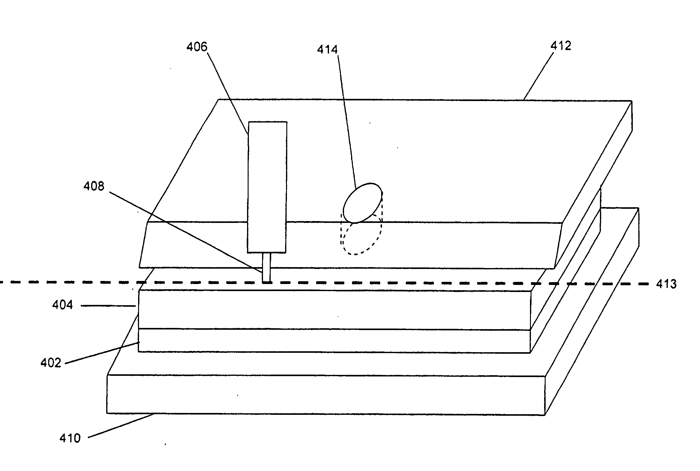
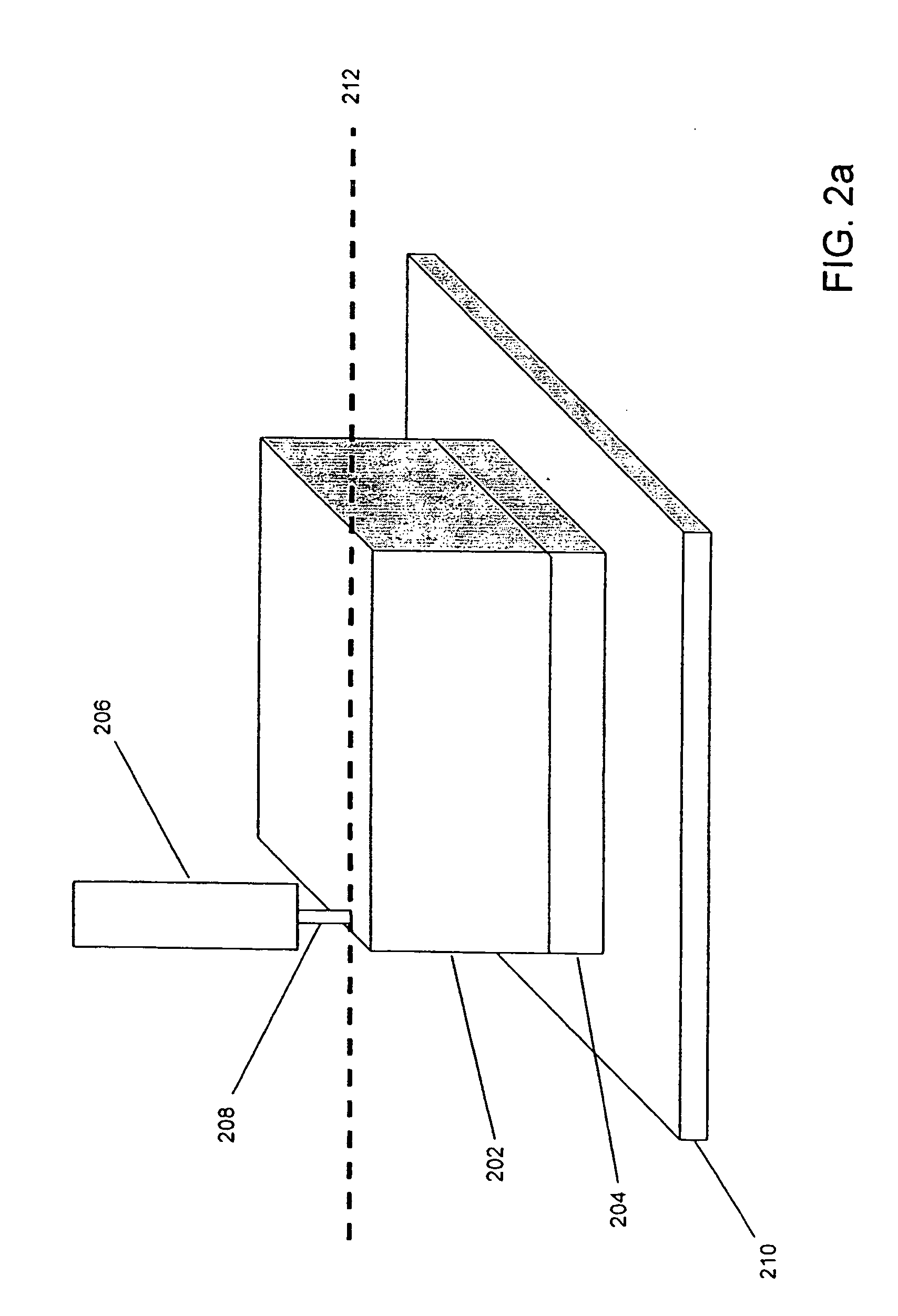
[0018] In FIG. 2a, an exemplary embodiment of the invention is shown as a welding setup including a top foil 202 positioned over a bottom foil 204. These foils are further positioned over support plate 210. To obtain an edge weld between top foil 202 and bottom foil 204, a laser 206 is used to apply laser beam 208 across weld line 212. Weld line 212 may be positioned, for example, at a distance from the edge of top foil 202 so that the diameter of the resulting melt pool does not substantially reach the edge, where it may cause an undesirable beading of the top foil material. Alternatively, the welding conditions may be controlled such that the melt pool reaches the edge of top foil 202, but does not bead excessively. Additionally, it is noted that the present exemplary welding setup may also be used with the weld line located in a central portion of the foils.

[0019] In their article MICRO-WELDING OF THIN FOIL WITH DIRECT DIODE LASER (Proceedings of SPIE Vol. 5063 Fourth Internatio...


PUM

PropertyMeasurementUnit
poweraaaaaaaaaa
poweraaaaaaaaaa
wavelengthaaaaaaaaaa

Abstract

A method and apparatus, for welding together a pair of metal foils of different thickness. The method includes the steps of positioning a thin metal foil adjacent a thick metal foil and applying a continuous wave laser beam to the thick metal foil to weld at least a portion of the thick metal foil and the thin metal foil together. A thermally conductive plate is positioned proximate the weld line in order to limit the thick foil melt pool and to function as a laser beam block. Accordingly, appropriate materials may be chosen for the foils and top plate so that the continuous wave laser beam couples optimally into the thick foil material and minimally into the top plate material. A thermocouple may be placed proximate the weld line to obtain measures of temperature used to vary the laser beam power and / or the slew rate.

Description

FIELD OF THE INVENTION [0001] The present invention relates to the field of welding and, more particularly, to a method and system for welding together two or more metal foils. BACKGROUND OF THE INVENTION [0002]FIG. 1 depicts a typical laser welding setup for laser welding together two metal foils of different thicknesses. As illustrated, a thin metal foil 102 is positioned on top of a thick metal foil 104. A laser 106 produces a pulsed laser beam 108 that is directed onto a top surface of the thin metal foil 102 along weld line 116. The laser beam 108 heats the thin metal foil 102 to its melting point, which, in turn, melts a portion of the thick metal foil 104 via conduction to form a “melt pool” containing metal from both metal foils 102, 104. In addition, the pulsed laser beam 108 effectively thrusts portions of the thin metal foil 102 into the thick metal foil 104. Moving the laser beam 108 allows the melt pool to cool, thereby binding the metal foils together. [0003] A support...

Claims


Application Information

Patent Timeline
Patent Type & Authority Applications(United States)
IPC IPC(8): B23K26/24B23K26/08B23K26/10B23K26/14
CPCB23K26/034B29C66/472B23K26/0869B23K26/10B23K26/125B23K26/1405B23K26/1458B23K26/246B23K2203/02B23K2203/08B29C65/1616B29C66/1122B29C66/43B29C66/73521B29C66/91221B29C66/939B29K2905/02B29K2905/10B29K2909/02B29K2995/0013B23K26/083B29C66/934B29C66/919B29C66/836B29C66/961B29C66/9161B29C65/44B29C66/742B29C65/1629B29C65/1654B29C65/1674B29C65/1687B29C66/91411B29C66/91431B29C66/9121B29C65/00B29C66/91421B23K26/1462B23K26/142B23K26/244B29C66/8122B23K2103/02B23K2103/04B23K2103/08B23K2103/10B23K2103/12B23K2103/172B23K2103/26
Inventor GREIG, CHRISTIAN F.
Owner PANASONIC CORP
Why Eureka
Try Eureka