Method for suppressing common mode noise

a common mode and noise technology, applied in the direction of transformer/inductance details, continuous variable inductance/transformers, emergency protective circuit arrangements, etc., can solve the problem of secondary side creating a larger common mode noise than that produced, and the size of the common mode is still a big problem, so as to reduce the common mode noise

Active Publication Date: 2007-07-26
DELTA ELECTRONICS INC
View PDF6 Cites 37 Cited by
  • Summary
  • Abstract
  • Description
  • Claims
  • Application Information

AI Technical Summary

Benefits of technology

[0011] The electrostatic shield may have a length-orientation gap region as shown in FIG. 3. Adjusting the length of the gap can change the parasitic capacitance Cp & Cs so as to meet the equation Vp*Cp=Vs*Cs thus reduce common mode noise. For example, when the top view of the transformer is a circle, wherein l1 is the length of the electrostatic shield, l2 is the length of the gap region, l1 and l2 are determined by the equations l1=(2π−θ)*d / 2, l2=θ*d / 2 respectively, wherein the θ, d represent gap angle of the gap region and diameter of the electrostatic shield respectively.
[0012] And the electrostatic shield can also have a width-orientation gap region x, y as shown in FIG. 5, adjusting x, y to reduce common mode noise, wherein x+y≧2 mm.
[0013] And part of the acreage of the shield can be replaced by another kind of material e.g. those whose permittivity is different from that of the shield adjusting the acreage of the the area to reduce common mode noise.
[0015] The present invention also discloses another embodiment for reduction of common mode noise. For a power converter, noise voltages which have jump point and static point is produced for the turning on and off of the switches. Adding a balancing capacitor between the jump point and static point of the noise voltage can reduce the common mode noise.

Problems solved by technology

In general, conductive EMI noise comprises differential mode noise and common mode noise.
Nowadays, though the common mode inductor and Y cap can be used to reduce the common mode noise, the size of them is still a big problem in the high requirement of power density of power supply.
Basing on our research, voltage jump of secondary side also affects common mode noise, especially when using normal Faraday shield, voltage jump of the secondary side may create a larger common mode noise than that produced by voltage jump of the primary side.

Method used


Image

  • Method for suppressing common mode noise
  • Method for suppressing common mode noise
  • Method for suppressing common mode noise

Examples


Embodiment Construction

[0026] In the following description, numerous specific details are set forth in order to provide a thorough understanding of the present invention, and the scope of the present invention is expressly not limited but expected as specified in the accompanying claims. One skilled in the relevant art will recognize, however, that the invention may be practiced without one or more of the specific details. In other instances, well known structures, materials, or operations are not shown or described in order to avoid obscuring aspects of the invention.

[0027] Those of ordinary skill in the art will immediately realize that the embodiments of the present invention described herein in the context of methods and schematics are illustrative only and are not intended to be in any way limiting. Other embodiments of the present invention will readily suggest themselves to such skilled persons having the benefits of this disclosure.

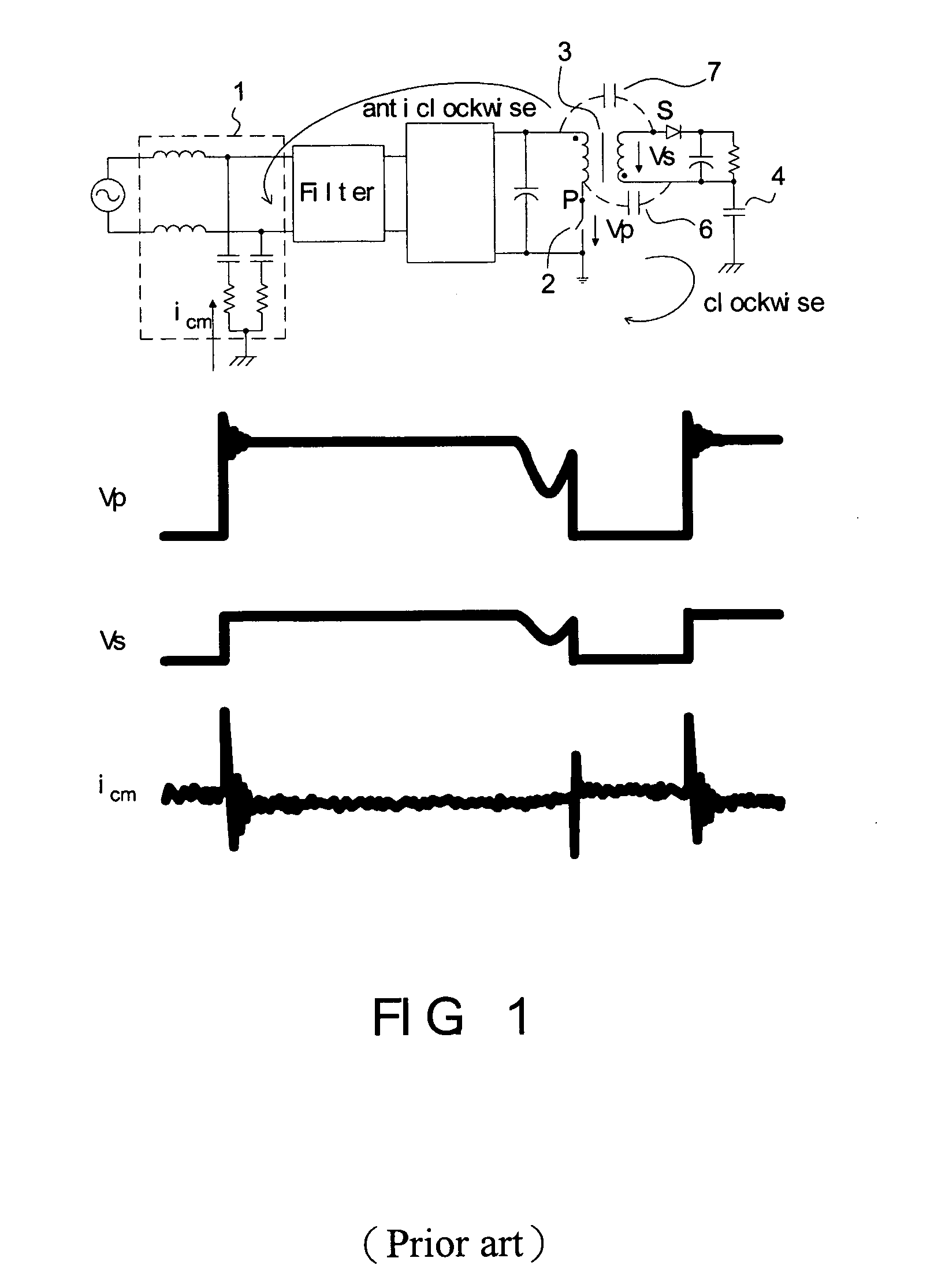
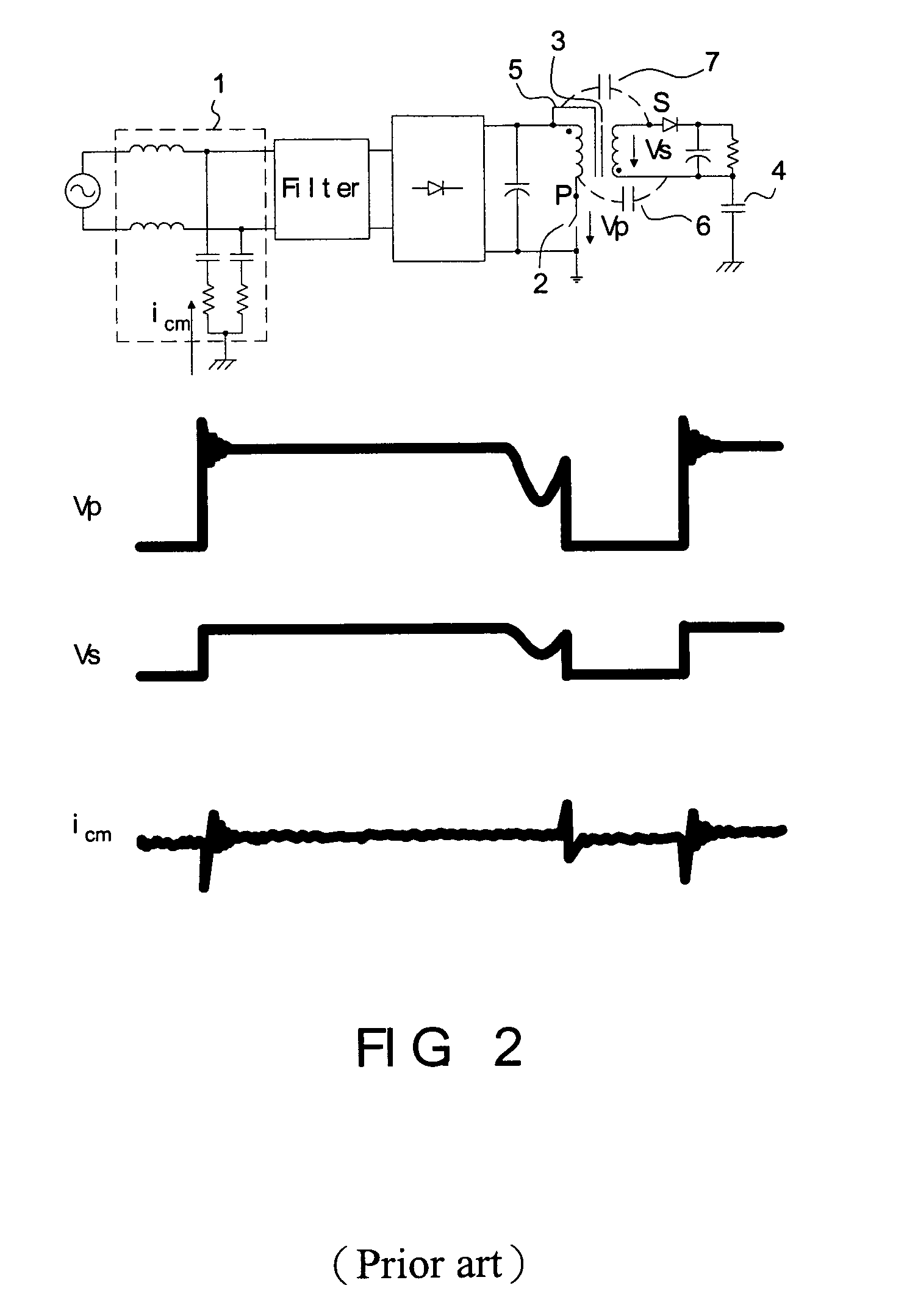
[0028] As it is well known that a power converter having a trans...


PUM


Abstract

The present invention discloses a power converter with low common mode noise. The power converter having a primary side and a secondary side, comprises a transformer having a primary winding and a secondary winding, and at least one electrostatic shield disposed between the primary winding and the secondary winding, wherein the electrostatic shield is configured with partial first region of the primary winding and partial second region of the secondary winding such that the electrostatic shield partially shields with the primary winding and the secondary winding to reach the purpose of suppressing the common mode noise. In addition, another method can be used to reduce the common mode noise of a power converter having primary side and secondary side, which is adding some additional impedance between the static points and jump points of the primary side and secondary side.

Description

BACKGROUND OF THE INVENTION [0001] 1. Field of the Invention [0002] The present invention relates to methods for suppressing common mode noise of the power converter. [0003] 2. Description of the Related Art [0004] Currently, switching mode power supply must meet EMI international standard such that filters become necessities. In general, conductive EMI noise comprises differential mode noise and common mode noise. The current-loop of the differential mode noise is formed between Live wire (L) and Neutral (N) wire, and its value is related to the magnitude of ripple current of input of the power supply. The current-loop of the common mode noise is formed between power supply Live wire (L) / Neutral (N) wire and ground, and which is produced by high current (i=C*dv / dt) of discharging and charging on parasitic capacitors. In filter design, the differential mode noise can be suppressed by differential mode inductor and X capacitor, and the common mode noise can be suppressed by common mo...

Claims


Application Information

Patent Timeline
Patent Type & Authority Applications(United States)
IPC IPC(8): H02H7/04
CPCH01F21/10H01F27/34H01F27/362H03H2001/0092H02M1/44H02M2001/123H02M1/12H01F27/36H02M1/123H01F27/363
Inventor SICONG, LINMIN, ZHOUPING, HE JUNCHEN, WEIYING, JIANPING
Owner DELTA ELECTRONICS INC
Why Eureka
Try Eureka