Scroll-type fluid displacement apparatus with fully compliant floating scrolls

a fluid displacement apparatus and scroll technology, applied in the direction of liquid fuel engines, rotary/oscillating piston pump components, machines/engines, etc., can solve the problems of high production cost, non-traditional thrust bearings are technically complicated and expensive, and fast wear of parts, so as to reduce friction wear and loss

Active Publication Date: 2007-07-26
NI & ASSOC
View PDF47 Cites 25 Cited by
  • Summary
  • Abstract
  • Description
  • Claims
  • Application Information

AI Technical Summary

Benefits of technology

[0009] In another embodiment, an orbiting scroll is driven by a driving shaft via a dual radial ball bearing structure to assure that each bearing bears only radial load to extend the bearing life.
[0011] In another embodiment, an orbiting dual thrust ball bearing mechanism in a floating scroll device to further reduce friction wear and loss caused by axial thrust force.

Problems solved by technology

This excursion can cause fast wear of the parts in oil-free environment.
In addition, a non-traditional thrust bearing is technically complicated and costly to produce.

Method used


Image

  • Scroll-type fluid displacement apparatus with fully compliant floating scrolls
  • Scroll-type fluid displacement apparatus with fully compliant floating scrolls
  • Scroll-type fluid displacement apparatus with fully compliant floating scrolls

Examples


first embodiment

[0048] The CSPS mechanism can also be applied in single floating scroll structure. a single floating scroll compressor with CSPS mechanism is shown in FIG. 8. In a single floating scroll structure the CSPS mechanism may be seen as a half of the mechanism in a dual scroll structure. The difference is that the plenum seal 68 (see FIG. 2) is static in a dual floating scroll structure, but dynamic in a single floating scroll structure (68 in FIG. 8).

[0049] Referring to FIG. 8, the compressor unit 10 includes a main housing 20, base housing 70, hermetic sealed motor 35, central drive shaft 40, fixed scroll 50 and orbiting scroll 60. Central drive shaft 40 consists of central rod 41 and crank pin 42. Central rod 41 is rotatably supported by bearing 33 and 34, and rotates along its axis S1-S1 when driven by hermetic sealed motor 35. An axial hole 43 in the middle of crank pin 42 is to balance the centrifugal force of the crank pin 42 when shaft 40 rotates along axis S1-S1. Hole 43 can also...

second embodiment

[0057] Referring to FIG. 9, in the second embodiment the plenum sealing mechanism comprises of an orbiting moving piston 68, an “O” ring 71 and spring 72. The orbiting moving piston 68, energized by spring 72 and air at discharge pressure in plenum chamber 83, can move axially and orbits together with orbiting scroll 60 against surface 73 of base housing 70. This mechanism seals off plenum 83 from suction area 81. Orbiting moving piston 68 is self-compensate to improve the life of the sealing mechanism.

[0058] In the third embodiment of single floating scroll of CSPS mechanism with a stationary moving piston seal mechanism as shown in FIG. 10, the plenum sealing elements, i.e. moving piston 71 and “O” ring 72, are stationary instead of orbiting together with orbiting scroll 60 as in the first and second embodiments. Sealing surface 73 of piston 71 energized by “O” ring 72 keeps light contact with sealing surface 65 of orbiting endplate 61 during operation. This mechanism seals off pl...

fourth embodiment

[0059] The friction wear and friction power loss resulted from axial forces in a floating scroll device, particularly when the pressure differential between the discharge gas and the suction gas is large, needs to be further reduced to improve the energy efficiency and durability. the single floating scroll device, an expander as shown in FIG. 11, provides an orbiting dual thrust ball bearing structure to bear the thrust load on orbiting scroll with a semi-radial compliant CSPS mechanism.

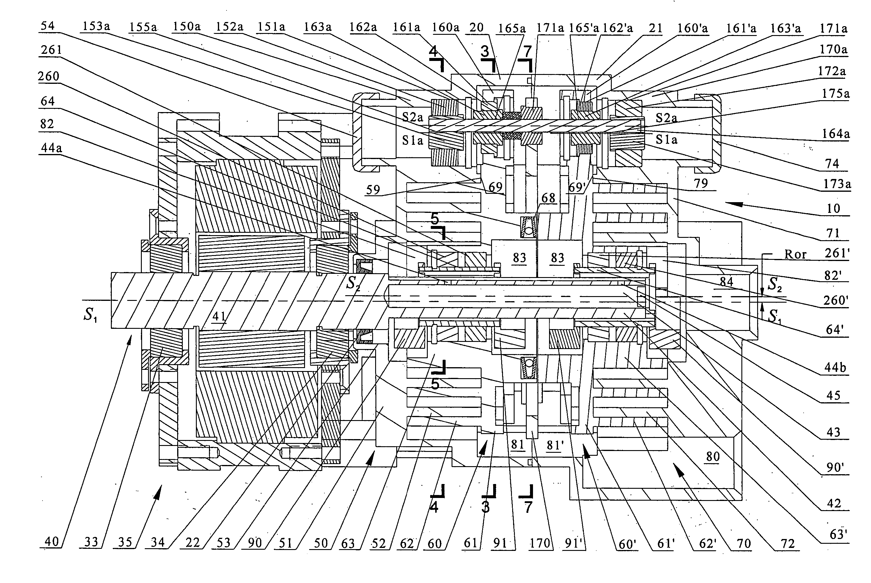
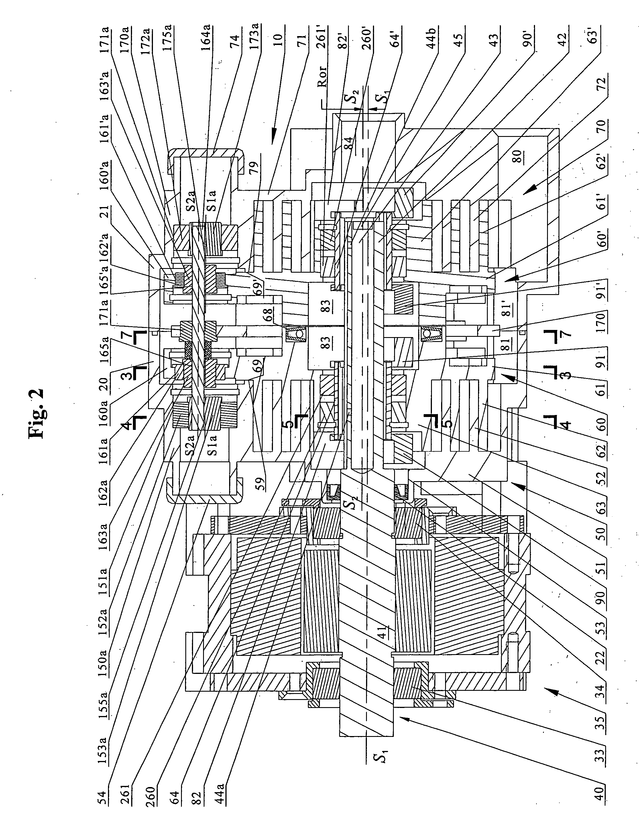
[0060] Referring to FIG. 11 expander unit 10 includes a main housing 20, rear housing 21, base housing 70, central drive shaft 40, fixed scroll 50 and orbiting scroll 60. Central drive shaft 40 consists of central rod 41 and crank rod 42. Central rod 41 is rotatably supported by bearing 33 and 34, and rotates along its axis S1-S1. Fixed scroll member 50 has an end plate 51 from which a scroll element 52 extends. Orbiting scroll member 60 includes circular end plate 61, scroll element 62 affixed to a...


PUM


Abstract

A central drive shaft-sliding knuckle combined with a peripheral crank pin-swing link mechanism (CSPS) to provide an orbiting scroll with radial and axial compliant capability. The CSPS mechanism can be applied to both dual floating scroll and single floating scroll structures to improve performances of scroll devices, particularly in oil-free operations. In addition, an orbiting dual thrust ball bearing mechanism is provided to take thrust load in, for example, a floating scroll compressor with a CSPS mechanism.

Description

FIELD OF THE INVENTION [0001] The invention relates to a scroll-type positive fluid displacement apparatus and more particularly to a scroll-type apparatus having an improved axially and radially compliant floating scroll mechanism. BACKGROUND OF THE INVENTION [0002] There is known in the art a class of devices generally referred to as “scroll” pumps, compressors and expanders, wherein two interfitting spiroidal or involute spiral elements are conjugate to each other and are mounted on separate end plates forming what may be termed as fixed and orbiting scrolls. These elements are interfitted to form line contacts between spiral elements. [0003] A pair of adjacent line contacts and the surfaces of end plates form at least one sealed off pocket. When one scroll, i.e. the orbiting scroll, makes relative orbiting motion, i.e. circular translation, with respect to the other, the line contacts on the spiral walls move along the walls and thus changes the volume of the sealed off pocket. ...

Claims


Application Information

Patent Timeline
Patent Type & Authority Applications(United States)
IPC IPC(8): F01C1/02F01C1/063
CPCF01C17/06F04C29/0057F04C29/0021F04C23/001F16C2360/42
Inventor NI, SHIMAO
Owner NI & ASSOC
Why Eureka
Try Eureka