Visual fiber placement inspection

a technology of visual inspection and automated fiber placement, which is applied in the direction of instruments, investigating composite materials, and material analysis, can solve the problems of high difficulty, high difficulty, and high difficulty involved, and achieve the effect of simple and elegant process, and eliminating the need for tedious computation

Active Publication Date: 2007-07-26
INGERSOLL MACHINE TOOLS
View PDF15 Cites 28 Cited by
  • Summary
  • Abstract
  • Description
  • Claims
  • Application Information

AI Technical Summary

Benefits of technology

[0029]Regardless of the particular type of sensing or detection device used in practicing the invention, a visual image, as viewed by the sensing or detection device, is processed in an entirely different, elegantly simple, and straightforward way, in the present invention as compared to prior art, such as Kitson, to substantially directly compare an overall viewed image of an area of the composite structure to a virtual overall image of the same area, in a manner that eliminates the need for tedious computations req...

Problems solved by technology

From the foregoing description, it will be appreciated that fabrication of a composite structure by automated fiber placement is a highly complex process, requiring considerable upfront effort during design of the structure, associated production tooling, and in setting up the automated fiber placement machine, to ensure that each and every tow of material is properly placed during the automated fiber placement process, in a manner that will result in a structure having a desired geometry and structural properties.
Due to the complexity involved in both the design and production of the composite structure by automated fiber placement, it is common practice to utilize computerized tools for both designing the structure, and in programming the automated fiber placement machine to properly move and operate the robotic fiber placement head, feed out material, cut and add tows, and in some cases to also move the tooling in synchronization with the robotic head during automated lay-up of the composite structure on the tooling.
Even after the composite structure, the tooling, and the automated fiber placement machine are designed and set up to provide for proper placement of the tows during fabrication, problems inherent in the production of composite structures make it necessary that the resulting composite structure be closely inspected to ensure that each and every tow wa...

Method used


Image

  • Visual fiber placement inspection
  • Visual fiber placement inspection
  • Visual fiber placement inspection

Examples


Embodiment Construction

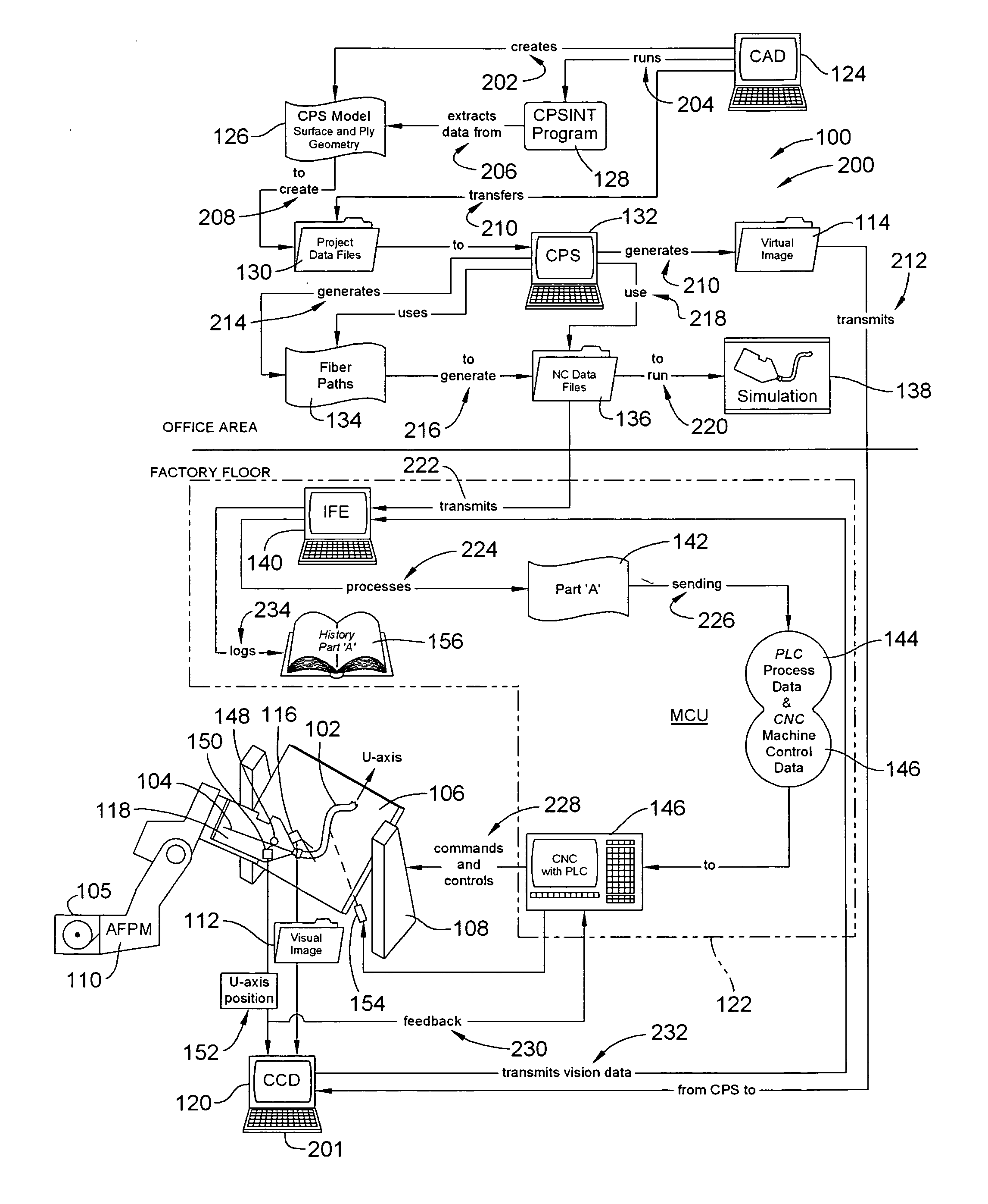
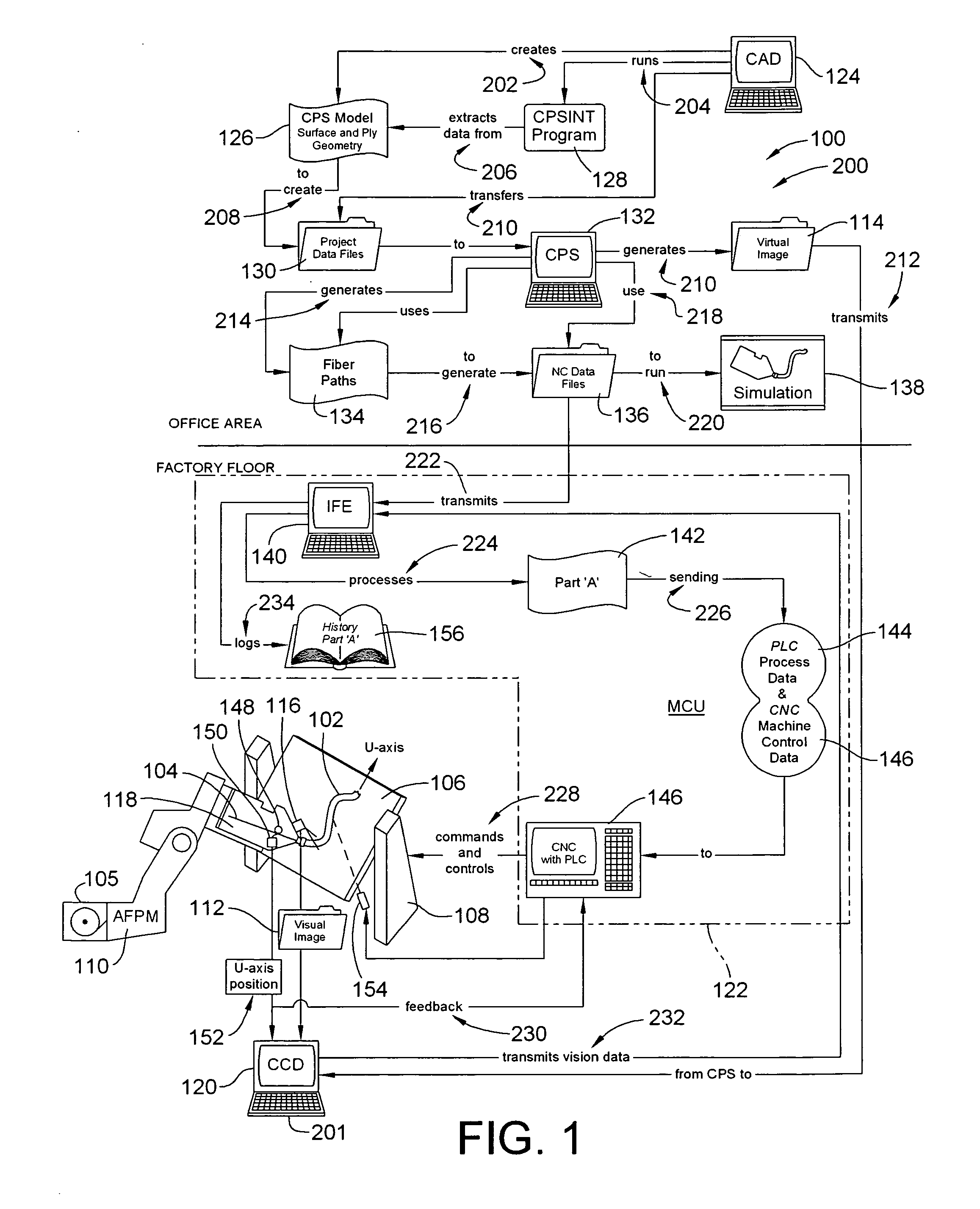
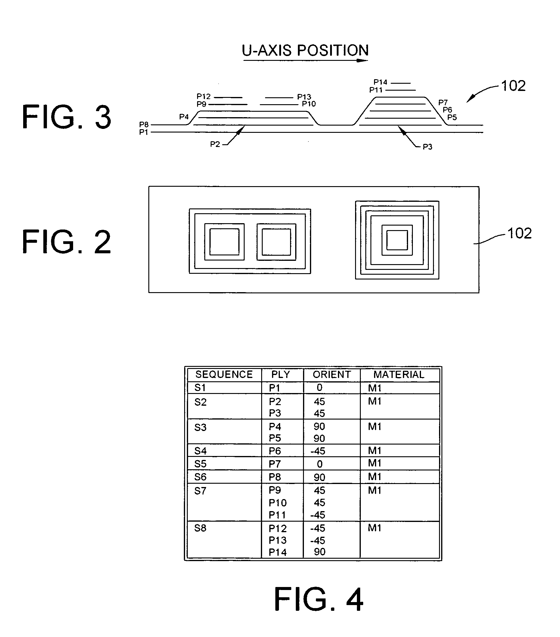
[0042]FIG. 1 is a combined schematic and flowchart illustrating a first exemplary embodiment of an apparatus 100 and a method (200) for inspecting a composite structure 102, formed from one or more composite tows 104, fed from a creel 105, and laid onto a tool surface 106 of a moveable tool 108 by an automated fiber placement machine (AFPM) 110, by comparing (201) a visual image 112 of at least a portion of the composite structure 102 to a virtual image 114 of the portion of the composite structure 102 captured in the visual image 112.

[0043]As will be described in more detail below, the virtual image 114 provides a theoretical rendering of the way that each tow in each layer of the composite structure should appear, in accordance with the design of the structure 102, to a vision capture element 116, which is operatively or physically mounted to a fiber placement head 118 of the AFPM 110, to view the fiber tows 104, as they are sequentially laid onto the tool surface 106 or on top of...


PUM

PropertyMeasurementUnit
Fractionaaaaaaaaaa
Fractionaaaaaaaaaa
Angleaaaaaaaaaa

Abstract

An apparatus and method are provided for performing, on-the-fly, real time inspection of a composite structure formed by an automated fiber placement machine, through comparison of a visual image of at least a portion of the composite structure to a virtual image of the composite structure. Proper formation of the structure, and/or anomalies within the structure, are determined by comparing the visual image to the virtual image. The automated fiber placement machine, and/or tooling upon which the fiber is placed, are manipulated, and a visual indicator are provided to facilitate inspection and/or repair of any detected anomalies during fabrication of the composite structure.

Description

FIELD OF THE INVENTION[0001]This patent application claims the benefit of U.S. Provisional Patent Application No. 60 / 761,664, filed Jan. 24, 2006, the disclosure and teachings of which are incorporated herein in their entireties.[0002]This invention is related to the use of automated fiber placement machines for fabrication of composite structures, and more particularly to performing visual inspection of the composite structure during the automated fiber placement process.BACKGROUND OF THE INVENTION[0003]Automated fiber placement is a process that is widely used for fabricating composite structures from pre-impregnated composite materials, such as carbon fiber, fiber glass and Kevlar. The materials, for use in automated fiber placement, typically take the form of a strip or yarn of composite material impregnated with a resin, with such strips or yarns being commonly referred to as tapes or tows, those terms being used in a generally interchangeable manner herein.[0004]During automat...

Claims


Application Information

Patent Timeline
IPC IPC(8): G06F19/00
CPCB29C70/382B29C70/384G01N2021/8472B29C2037/906G01N21/8851B29C2037/903
Inventor OLDANI, TINO
Owner INGERSOLL MACHINE TOOLS
Why Eureka
Try Eureka