Exhaust gas collection device

a trap device and exhaust gas technology, applied in the direction of sustainable manufacturing/processing, final product manufacturing, and separation processes, can solve the problems of reducing the service life of the trap device, and reducing the maintenance cycle. , to achieve the effect of reducing the outflow of solidified components, suppressing uneven distribution, and excellent

Inactive Publication Date: 2007-08-02
TOKYO ELECTRON LTD
View PDF6 Cites 16 Cited by
  • Summary
  • Abstract
  • Description
  • Claims
  • Application Information

AI Technical Summary

Benefits of technology

[0018] In accordance with the present invention, it is possible to attain an excellent effect in realizing an exhaust trap device that can suppress uneven distribution in the amount of accumulation of so

Problems solved by technology

Such gas reaction apparatuses suffer from a problem that reaction by-products are solidified from the exhaust gas discharged out of the gas reaction chamber and are accumulated in the exhaust route or the evacuation device, which may lead to clogging of the exhaust route or failure of the evacuation device.
This makes it impossible to keep the gas reaction chamber arranged at the upstream side in a vacuum condition or causes clogging in the vicinity of entrance of the exhaust path, which in turn poses a problem that the exhaust trap device needs to be maintained at an increased frequency.
However, if the temperature in the exhaust path is raised, the reaction by-products cannot be sufficiently trapped in the exhaust trap device and the reaction by-products are solidified in an evacuation devic

Method used


Image

  • Exhaust gas collection device
  • Exhaust gas collection device
  • Exhaust gas collection device

Examples


Embodiment Construction

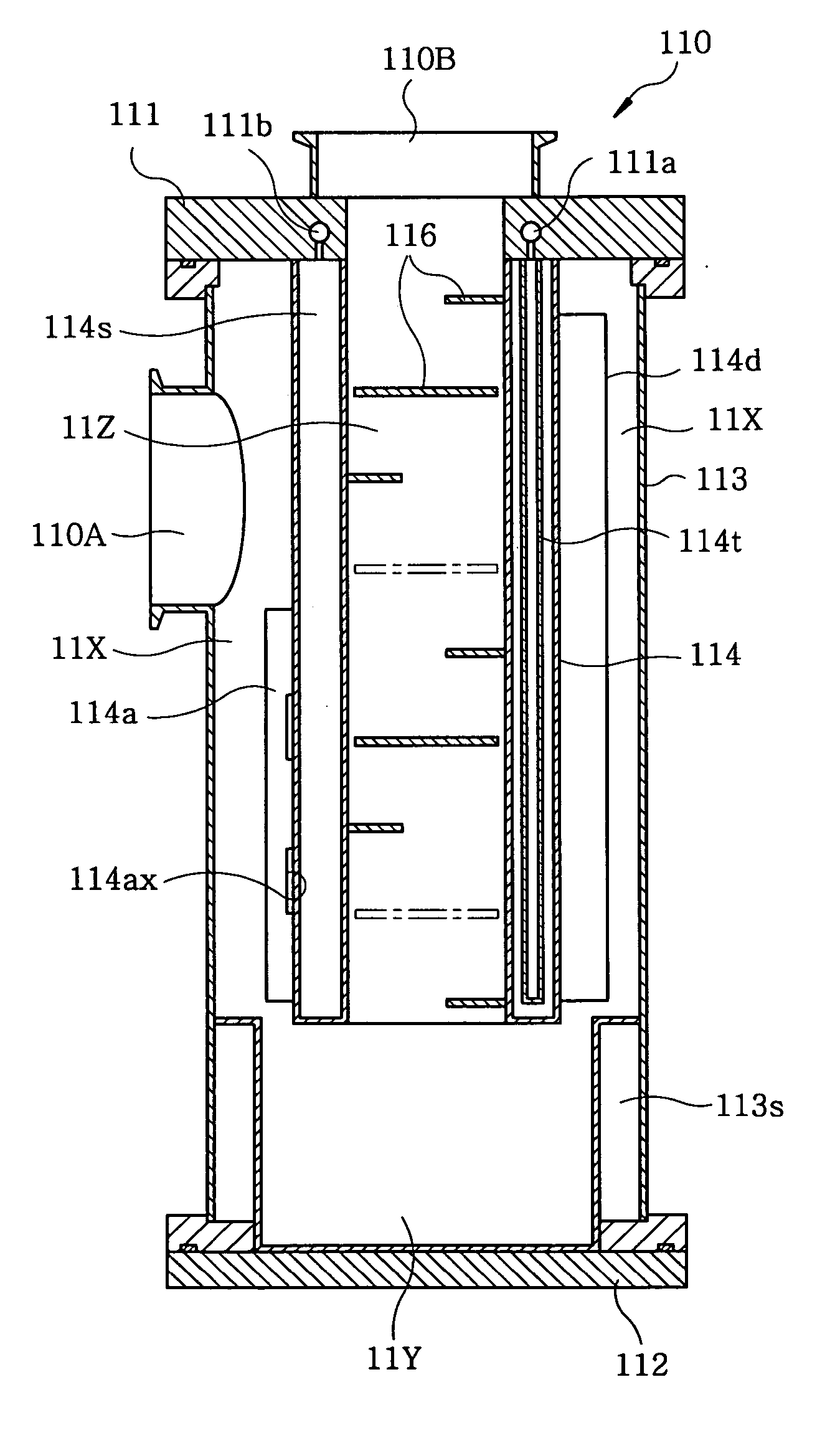
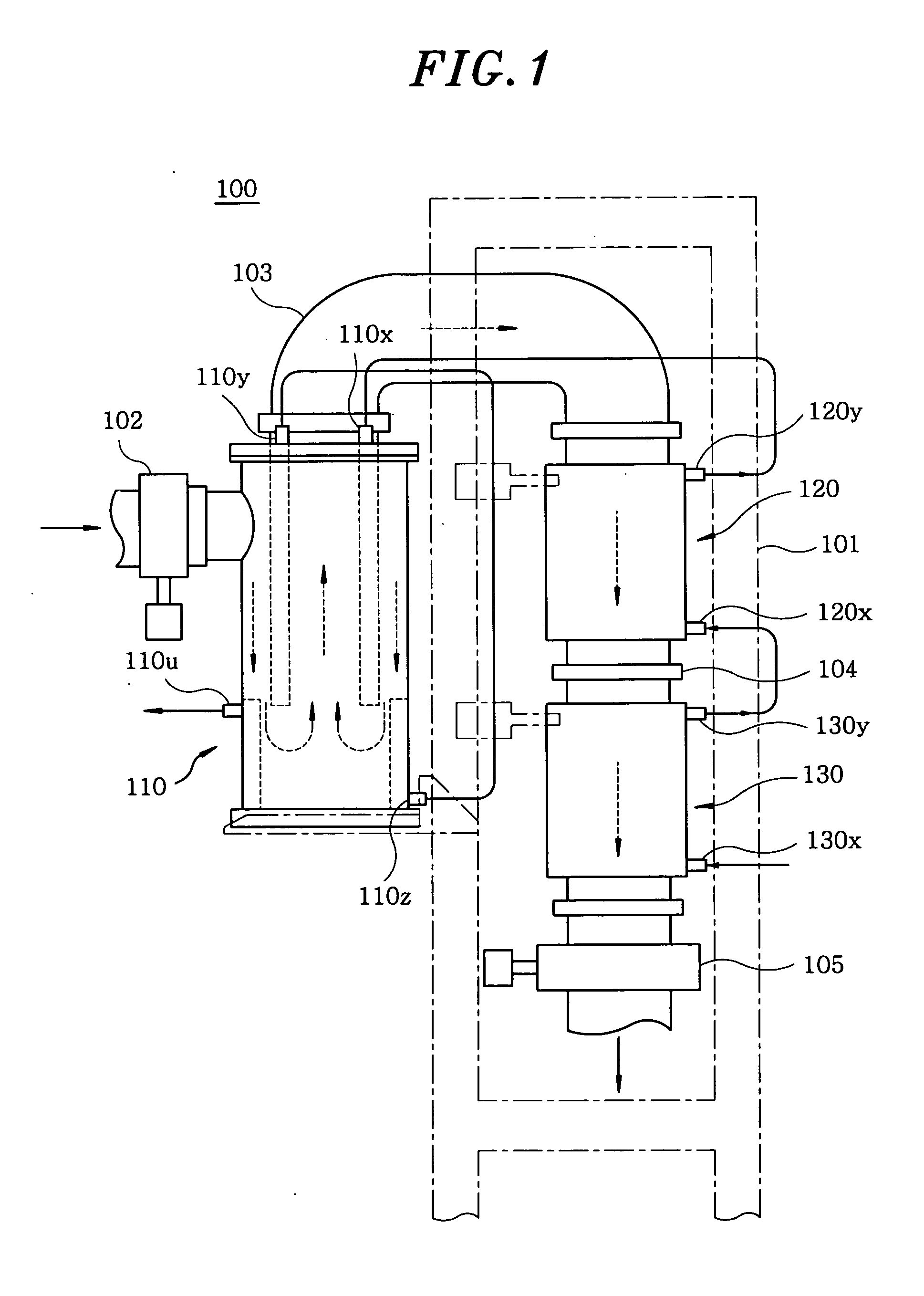
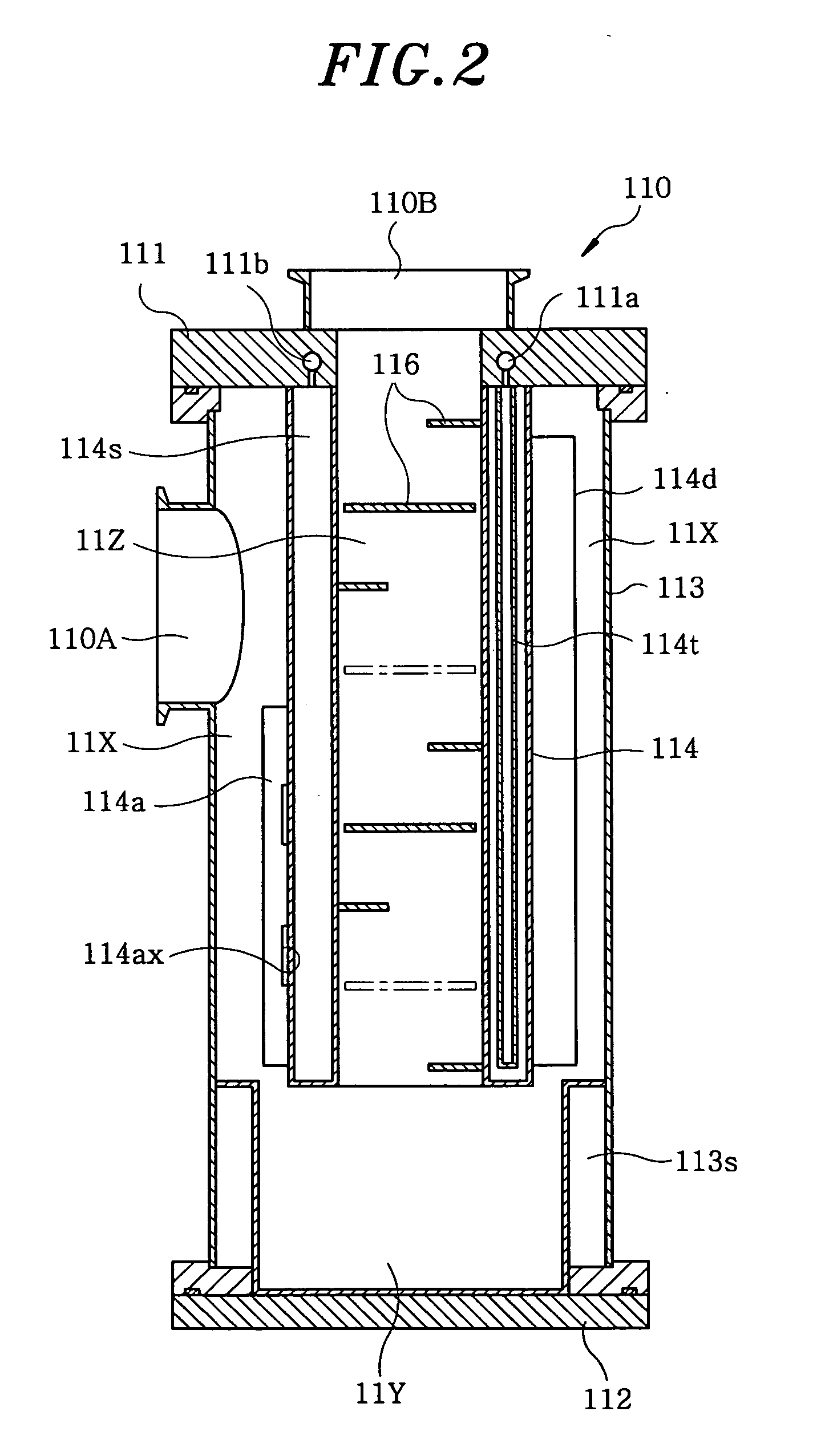
[0027] An embodiment of the present invention will now be described with reference to the accompanying drawings. FIG. 1 is a front view showing the overall configuration of an exhaust trap device 100 in accordance with an embodiment of the present invention. The exhaust trap device 100 includes a first trap unit 110, a second trap unit120 and a third trap unit 130 arranged in series along an exhaust route of a gas. The first trap unit 110, the second trap unit 120 and the third trap unit 130 are combined together as a single unit by means of a frame 101. Accordingly, each of the trap units can be separated by releasing them from the frame 101. The first trap unit 110 has a gas inlet port connected to a downstream side of a valve 102 which may be a butterfly valve. The first trap unit 110 has a gas outlet port connected to a gas inlet port of the second trap unit 120 through a “U”-shaped exhaust line 103. The second trap unit 120 has a gas outlet port connected to a gas inlet port of...


PUM

PropertyMeasurementUnit
Angleaaaaaaaaaa
Flow rateaaaaaaaaaa
Perimeteraaaaaaaaaa

Abstract

Exhaust gas collection units (110, 120, 130) are arranged in series in an exhaust gas collection device (100) for collecting objects separated from exhaust gas passing an exhaust gas route, and inside the exhaust gas collection units (110, 120, 130) are formed exhaust gas paths for passing exhaust gas along the exhaust gas route. Collision plates are placed in an exhaust gas collection section in each of the collection units. The collision plates in the exhaust gas collection sections of the upstream side collection units (110, 120) are arranged such that a space extending in the axial direction of the exhaust path is present in the exhaust path without being blocked by any of the collision plates arranged in the exhaust path. The collision plates in the exhaust gas collection section in the exhaust gas collection unit (130) on the downstream side are arranged so that such a space is not present. Uneven distribution of the amount of accumulation of separated objects such as reaction by-products are suppressed without performing complex control, and outflow of the objects to the downstream side of the exhaust gas collection device can be reliably reduced.

Description

FIELD OF THE INVENTION [0001] The present invention relates to an exhaust trap device; and, more particularly, to the structure of an exhaust trap device that exhibits enhanced trapping efficiency to thereby reduce outflow of solidified components toward a downstream side of the exhaust trap device. BACKGROUND OF THE INVENTION [0002] In general, various gas reaction apparatuses for forming films on a substrate or etching the substrate have been used as semiconductor manufacturing apparatuses. Typically, such a gas reaction apparatuses includes a gas supply unit, a hermetic gas reaction chamber supplied with a gas from the gas supply unit, an exhaust route connected to the gas reaction chamber and an evacuation device, such as a vacuum pump or the like, connected to the exhaust route. [0003] Such gas reaction apparatuses suffer from a problem that reaction by-products are solidified from the exhaust gas discharged out of the gas reaction chamber and are accumulated in the exhaust rou...

Claims


Application Information

Patent Timeline
IPC IPC(8): B01D45/00B01D53/46B01D8/00B01D45/08C23C16/44H01L21/00H01L21/205H01L21/31
CPCB01D45/08Y02C20/30H01L21/67109C23C16/4412Y02P70/50H01L21/00H01L21/02H01L21/20H01L21/3065
Inventor TSUJI, NORIHIKO
Owner TOKYO ELECTRON LTD
Why Eureka
Try Eureka