Dual technology sensor device with range gated sensitivity

a sensor and range gate technology, applied in the field of security systems, can solve the problems of pir sensor being more susceptible to noise and false alarms, pir sensor being more vulnerable to false alarms, and unit being very false alarm prone, so as to increase the performance of security devices, reduce false alarms, and increase the performance

Inactive Publication Date: 2007-08-02
HONEYWELL INT INC
View PDF9 Cites 36 Cited by
  • Summary
  • Abstract
  • Description
  • Claims
  • Application Information

AI Technical Summary

Benefits of technology

[0010] The present invention is a method and device for detecting an intruder in a region with increased performance and decreased false alarms. The security device has a microwave sensor and a PIR sensor operatively coupled to a processor. To increase the performance of the security device, the de...

Problems solved by technology

This causes the PIR sensor to be more susceptible to noise and false alarms.
A second problem with the PIR sensors occurs when the intruder walks directly at the PIR sensor (so-called “down the throat”) rather than across the field and through the sectors of the lens array.
In this case, the PIR may not detect the intruder.
An additional problem with PIR sensors is that the...

Method used


Image

  • Dual technology sensor device with range gated sensitivity
  • Dual technology sensor device with range gated sensitivity
  • Dual technology sensor device with range gated sensitivity

Examples


Embodiment Construction

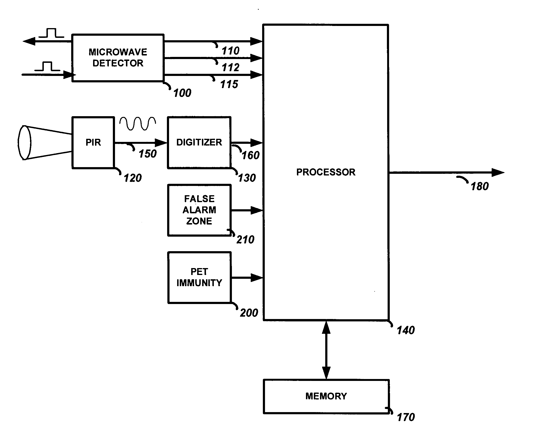
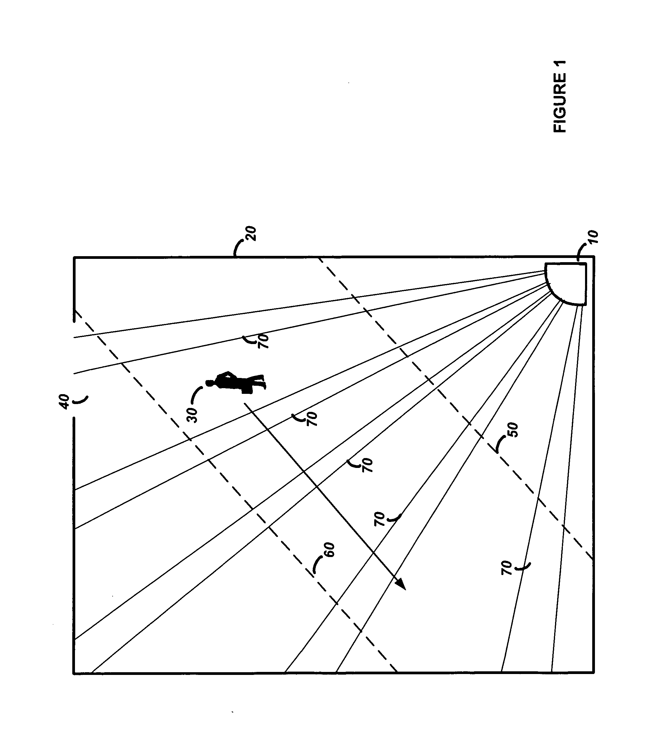
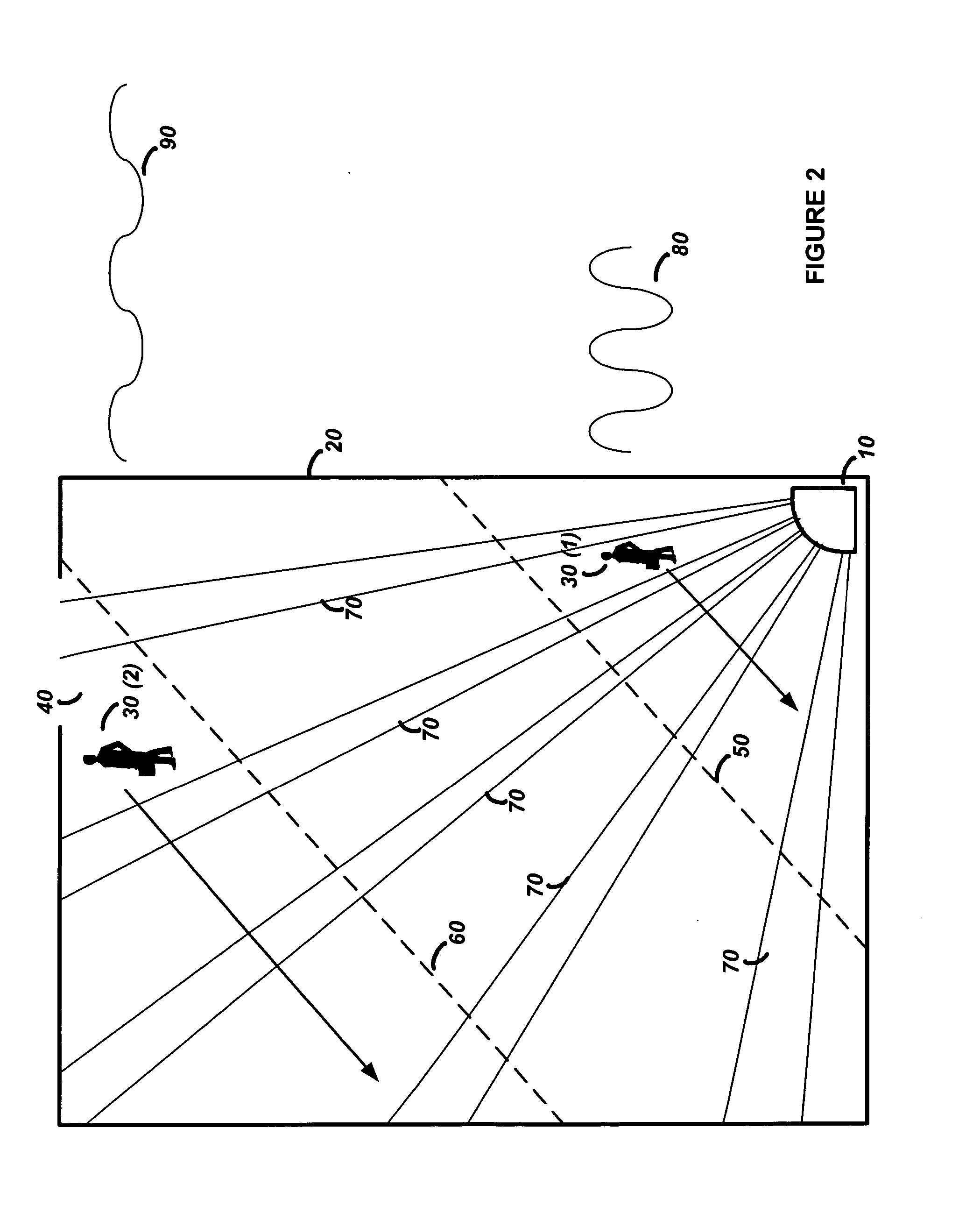
[0021] The preferred embodiments of the present invention will now be described with respect to the Figures. FIG. 1 illustrates a block diagram of the operation of the security device 10 in a region 20. The security device 10 is programmed, through adjustment of jumpers by the installer, with the size of the region 20 during installation. When the security device 10 is armed, it protects the region 20 by transmitting microwave pulses through the region and collecting the pulses that are reflected back to the security device 10. As the intruder 30 walks into the region 20 through the entrance 40, he causes the reflected microwave pulses to change. The security device 10 senses the change and determines if the intruder 30 is less than 9 feet (shown by line 50), greater than 9 feet but less than 18 feet (shown by line 60), or greater than 18 feet from the security device 10. The calculation of the distance information is determined from the jumper information (during installation) and ...


PUM


Abstract

A method and device for detecting an intruder in a region with increased performance and decreased false alarms. The security device has a microwave sensor and a PIR sensor operatively coupled to a processor. To increase the performance of the security device the device determines distance information of an object in the region with the microwave sensor, processes the distance information to adapt a frequency response of the PIR sensor to provide a frequency adapted PIR signal, and determines if the object is an intruder by using the frequency adapted PIR signal.

Description

TECHNICAL FIELD [0001] This invention relates to security systems, and in particular to a security device that uses a microwave detector for range determination to improve the performance of a PIR detector. BACKGROUND ART [0002] Security systems often employ the use of passive infrared (PIR) sensors for detecting motion in a region. A PIR sensor comprises a lens array that divides the protected region into sectors, a PIR detector that detects from each sector heat radiating from an object, and an amplifier / threshold detection circuit for determining if the detected heat is above a threshold producing an alarm condition. As an intruder passes through the protected region, the lens array collects and focuses the intruder's heat from each sector it passes through onto the PIR detector to produce a sine wave. The frequency of the sine wave corresponds to the speed of the intruder walking through the sectors, and the amplitude of the sine wave corresponds to the amount of heat collected ...

Claims


Application Information

Patent Timeline
IPC IPC(8): G08B19/00
CPCG08B13/19G08B29/183G08B13/2494
Inventor BABICH, THOMAS S.MARTIN, CHRISTOPHER D.
Owner HONEYWELL INT INC
Why Eureka
Try Eureka