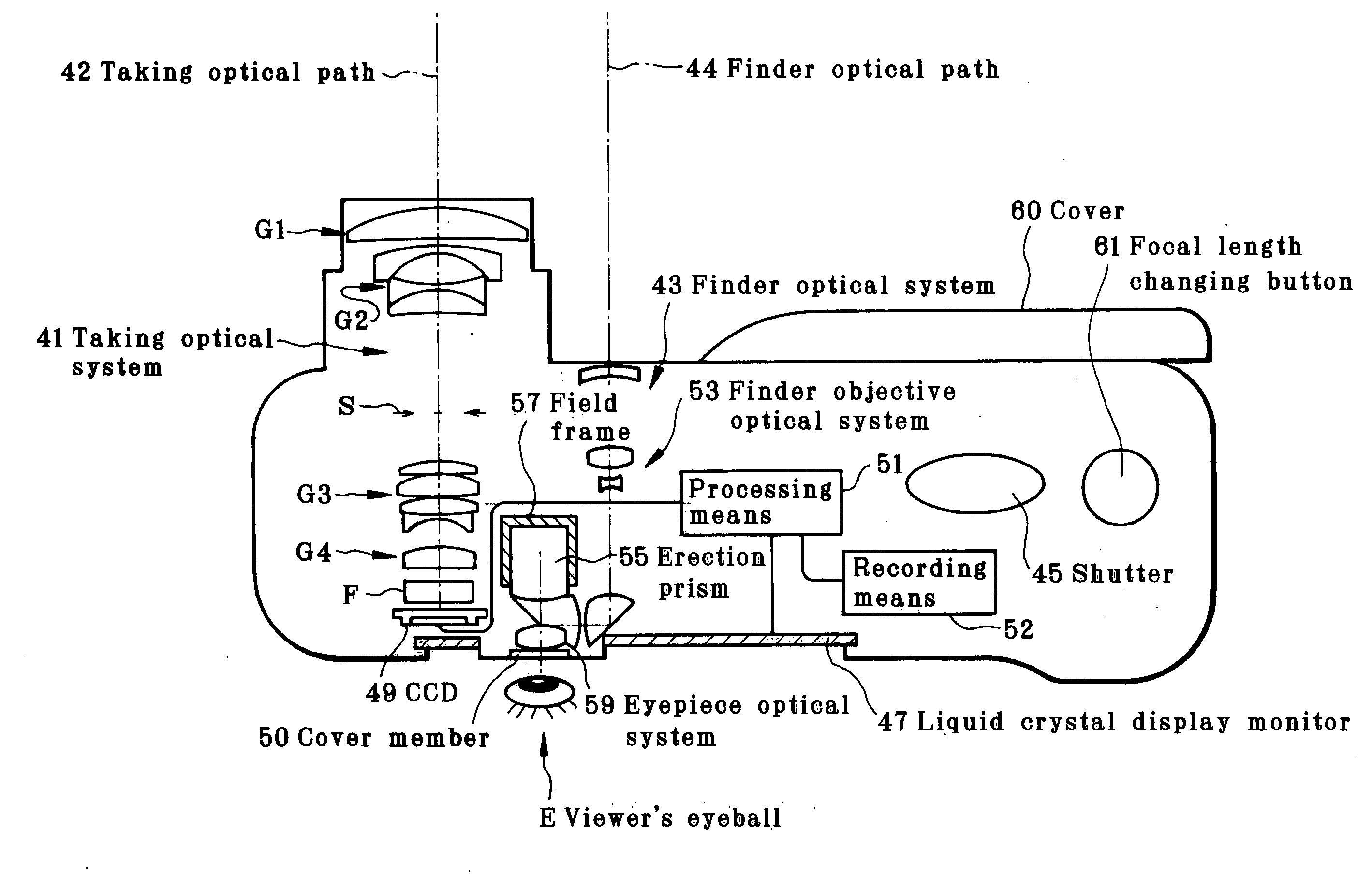
Taking apparatus

a technology of taking apparatus and a camera, which is applied in the field of taking apparatus, can solve the problems of insufficient resolution per frame, inability to take still pictures, and difficulty in downsizing the whole system, and achieves the effect of saving power, reducing size, and efficient attaining the quantity of light sensed

Inactive Publication Date: 2007-08-02
OM DIGITAL SOLUTIONS CORP
View PDF6 Cites 52 Cited by
  • Summary
  • Abstract
  • Description
  • Claims
  • Application Information

AI Technical Summary

Benefits of technology

[0014]In view of the aforesaid problems, the present invention has for its object the provision of an imaging apparatus which works for size reductions, power savings, the efficient attainment of the quantity of light sensed, and prevention of contrast decreases due to a diffraction phenomenon, is well fit for the taking and appreciation of common still pictures, and comprises a taking lens and electronic imaging device combination that takes full advantage of the characteristics of an imaging device.

Problems solved by technology

With the digital single-lens reflex camera, however, it is still difficult to downsize the whole system if the demanded image qualities and functions are factored in.
The former video camera of small size uses pixels only enough to maintain image quality during the taking of moving pictures or a limited number of substantial pixels, and so resolution per frame is insufficient and image quality is not worth still pictures as yet.
However, when it is intended to obtain pixels enough to allow for appreciation of good still pictures by use of a small-format electronic imaging device, the quantity of light sensed per pixel of the electronic imaging device tends to diminish and an exposure time tends to become long, rendering camera movement or subject movement likely to occur.
A limited imaging plane causes contrast to decrease under the influence of diffraction on the taking optical system and, hence, the image-formation capability of the taking optical system to become worse.

Method used


Image

  • Taking apparatus
  • Taking apparatus
  • Taking apparatus

Examples


example 1

[0113]

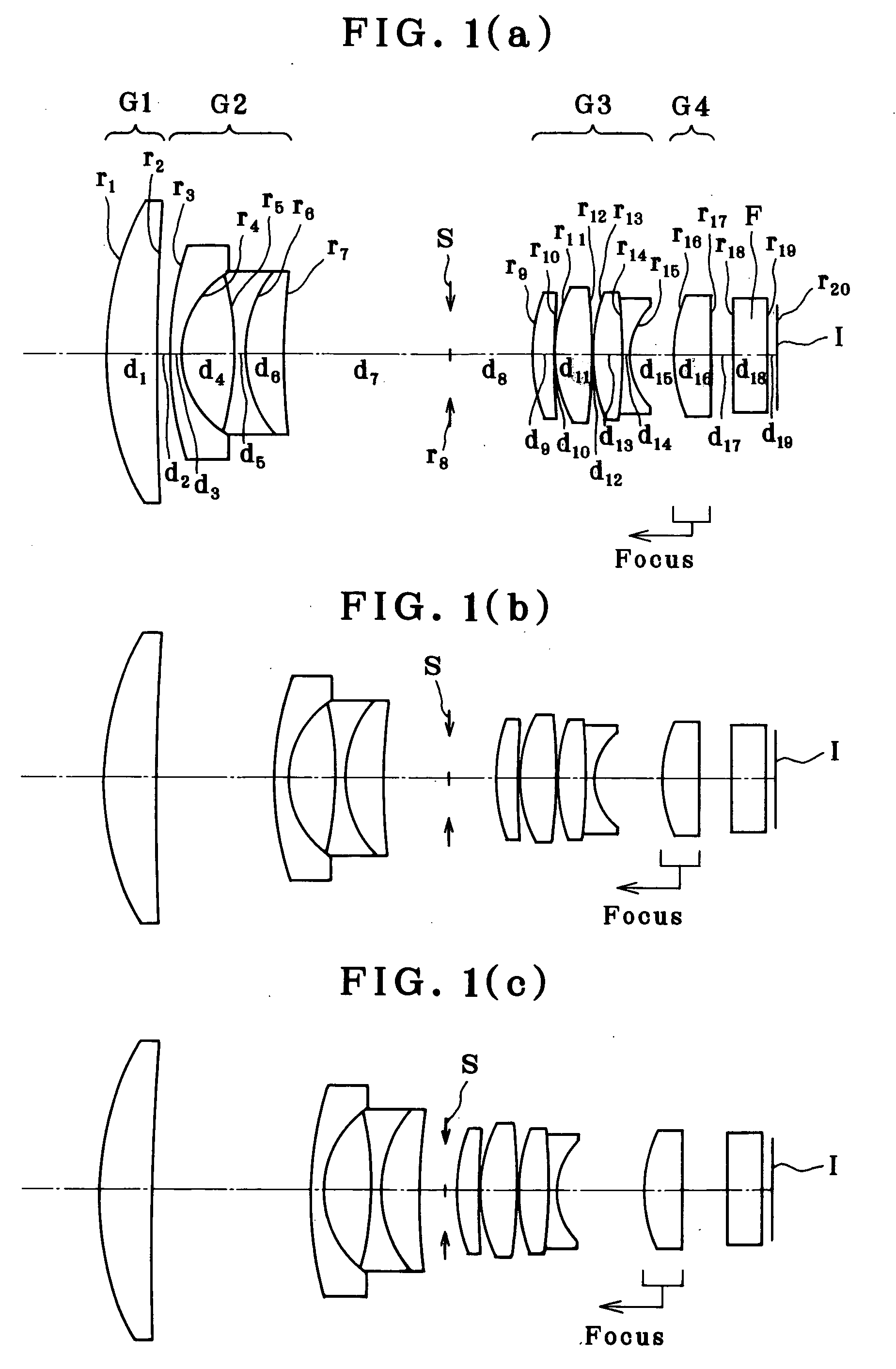
r1 = 22.693d1 = 3.807nd1 = 1.48749νd1 = 70.23r2 = 241.581d2 = (Variable)r3 = 25.064d3 = 1.01nd2 = 1.84666νd2 = 23.78r4 = 6.796d4 = 3.75r5 = −22.961d5 = 0.78nd3 = 1.48749νd3 = 70.23r6 = 8.805d6 = 2.84nd4 = 1.84666νd4 = 23.78r7 = 55.029d7 = (Variable)r8 = ∞ (Stop)d8 = (Variable)r9 = 14.023 (Aspheric)d9 = 1.47nd5 = 1.58913νd5 = 61.30r10 = 99.844d10 = 0.16r11 = 10.398d11 = 2.53nd6 = 1.77250νd6 = 49.60r12 = −53.227d12 = 0.16r13 = 12.435d13 = 2.12nd7 = 1.74100νd7 = 52.64r14 = −78.311d14 = 0.75nd8 = 1.84666νd8 = 23.78r15 = 5.016d15 = (Variable)r16 = 10.015d16 = 2.88nd9 = 1.69350νd9 = 53.22(Aspheric)r17 = 2588.080d17 = (Variable)r18 = ∞d18 = 2.72nd10 = 1.51633νd10 = 64.14r19 = ∞d19 = 0.78r20 = ∞(Image pick-up plane)Aspherical Coefficients9 th surfaceK = 1.005A4 = −9.8064 × 10⁻⁵A6 = −3.77082 × 10⁻⁸A8 = −3.46489 × 10⁻⁸A10 = 1.30338 × 10⁻⁹A12 = −1.73106 × 10−1116 th surfaceK = 0.334A4 = −4.85216 × 10⁻⁵A6 = −6.92172 × 10⁻⁷A8 = 1.48559 × 10⁻⁷A10 = −7.23748 × 10⁻⁹A12 = 1.17804 × 10⁻¹⁰Zoomin...

example 2

[0114]

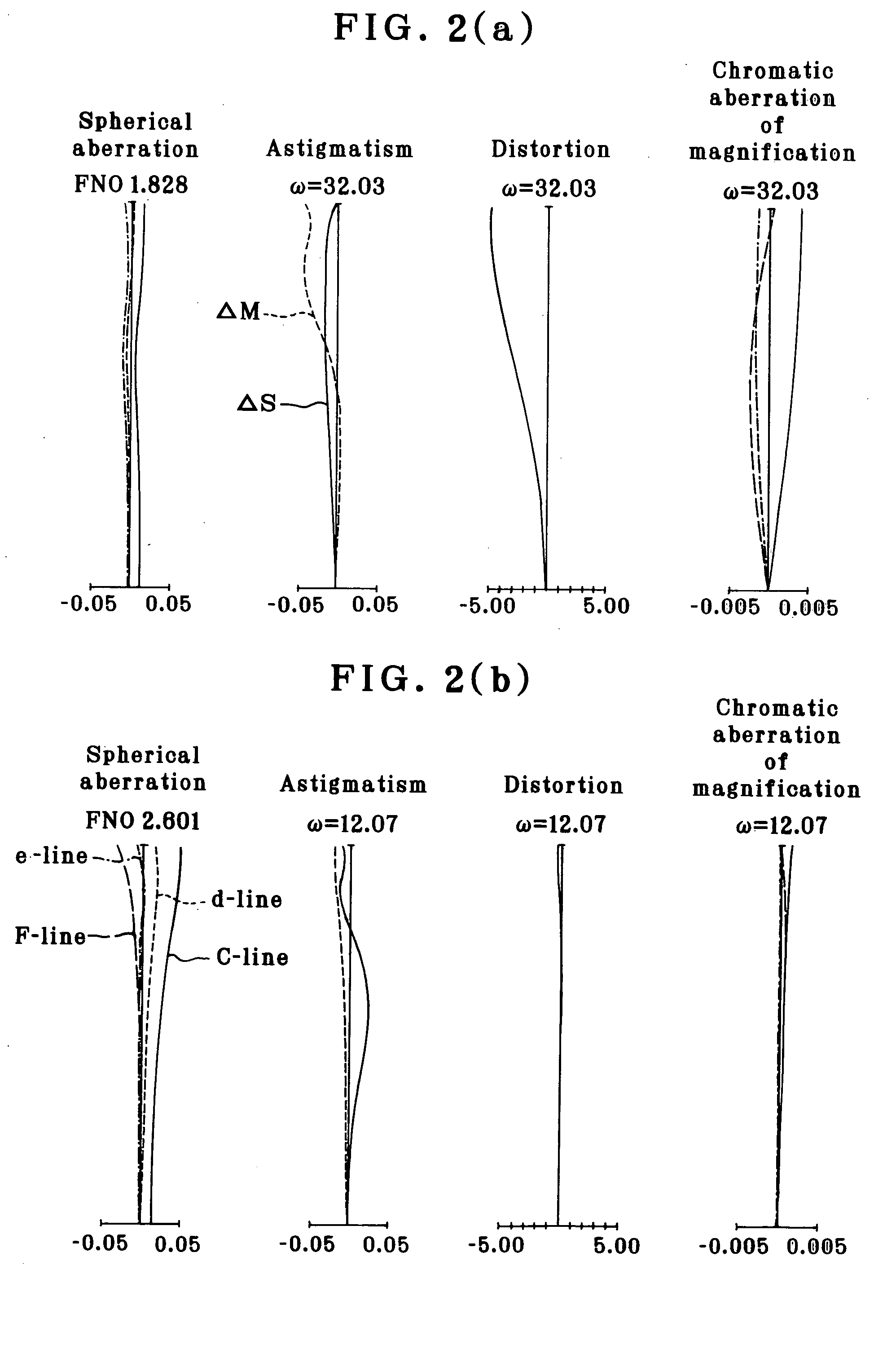
r1 = 22.693d1 = 3.807nd1 = 1.48749νd1 = 70.23r2 = 241.581d2 = 0.78r3 = 25.064d3 = 1.01nd2 = 1.84666νd2 = 23.78r4 = 6.796d4 = 3.75r5 = −22.961d5 = 0.78nd3 = 1.48749νd3 = 70.23r6 = 8.805d6 = 2.84nd4 = 1.84666νd4 = 23.78r7 = 55.029d7 = 12.67r8 = ∞ (Stop)d8 = 6.18r9 = 14.023 (Aspheric)d9 = 1.47nd5 = 1.58913νd5 = 61.30r10 = 99.844d10 = 0.16r11 = 10.398d11 = 2.53nd6 = 1.77250νd6 = 49.60r12 = −53.227d12 = 0.16r13 = 12.435d13 = 2.12nd7 = 1.74100νd7 = 52.64r14 = −78.311d14 = 0.75nd8 = 1.84666νd8 = 23.78r15 = 5.016d15 = 3.42r16 = 10.015d16 = 2.88nd9 = 1.69350νd9 = 53.22(Aspheric)r17 = 2588.080d17 = 1.76r18 = ∞d18 = 2.72nd10 = 1.51633νd10 = 64.14r19 = ∞d19 = 0.78r20 = ∞(Image pick-up plane)Aspherical Coefficients9 th surfaceK = 1.005A4 = −9.8064 × 10⁻⁵A6 = −3.77082 × 10⁻⁸A8 = −3.46489 × 10⁻⁸A10 = 1.30338 × 10⁻⁹A12 = −1.73106 × 10−1116 th surfaceK = 0.334A4 = −4.85216 × 10⁻⁵A6 = −6.92172 × 10⁻⁷A8 = 1.48559 × 10⁻⁷A10 = −7.23748 × 10⁻⁹A12 = 1.17804 × 10⁻¹⁰ω (°)32.03f (mm)5.75FNO1.83

[0115]In...


PUM


Abstract

The present invention concerns an imaging apparatus which works for size reductions, power savings, the efficient attainment of the quantity of light sensed, and prevention of contrast decreases due to a diffraction phenomenon, is well fit for the taking and appreciation of common still pictures, and comprises a taking lens and electronic imaging device combination that takes full advantage of the characteristics of an imaging device. The imaging apparatus comprises a taking optical system, and an electronic imaging device which is located on an image side of said taking optical system, includes an imaging plane I with a plurality of two-dimensionally arranged light sensors, and is adapted to convert an image formed through said imaging optical system into electrical signals. In at least one taking state, the apparatus satisfies at the same time condition (1) about relations of the area of the entrance pupil to the focal length of the taking optical system, condition (2) about the number of effective pixels of the imaging plane, condition (3) about the effective area of the imaging plane, and condition (4) about the division of the effective area of the imaging plane by the number of effective pixels.

Description

[0001]This application claims benefit of Japanese Application No. 2006-22795 filed in Japan on Jan. 31, 2006, the contents of which are incorporated by this reference.BACKGROUND OF THE INVENTION[0002]The present invention relates generally to a taking apparatus comprising an imaging optical system and an electronic imaging device such as CCD or CMOS, and more particularly to a digital camera or a video camera capable of reproducing still pictures.[0003]There has been an imaging apparatus known so far in the art, which makes use of an electronic imaging device such as CCD or CMOS, and converts an image formed through a taking optical system into electrical signals for recording, display, printing or other purposes.[0004]Such imaging apparatus have now a lot more versions from a single-lens reflex camera adapted to take still pictures in a full-scale way to a compact camera designed to be readily carried around due to its compactness.[0005]Of these, the so-called digital single-lens r...

Claims


Application Information

Patent Timeline
Patent Type & Authority Applications(United States)
IPC IPC(8): G02B13/16
CPCG02B13/001G02B13/0045G02B23/145G02B13/009G02B15/173G02B13/006G02B15/144113
Inventor GOTO, HISASHI
Owner OM DIGITAL SOLUTIONS CORP
Why Eureka
Try Eureka