Combustor liners

a technology of combustor liner and combustor plate, which is applied in the field of combustor plate, can solve the problems that the combustor plate cannot be applied over a weld, and the operation life of the welded joint between the combustor plate sections is extremely limited

Active Publication Date: 2007-08-09
ANSALDO ENERGIA SWITZERLAND AG
View PDF16 Cites 39 Cited by
  • Summary
  • Abstract
  • Description
  • Claims
  • Application Information

AI Technical Summary

Benefits of technology

[0009] The axially extending edges of the heat shield can include a u-shaped channel for receiving the retention flanges of the first and second liner sections. The heat shield can then be inserted into the space between the retention flanges of the first and second liner sections after the first parts have been joined together such that the retention flanges of the first and second liner sections are slidably received in the u-shaped channels defined by the axially extending edges of the heat shield. A sealing means can also be included to provide a seal between a surface of the heat shield and the retention flanges to prevent the hot ignition gases in the combustion chamber from entering the passage between the heat shield and the liner sections.
[0010] In the case where the axially extending edges of the heat shield define u-shaped channels, it will be appreciated that part of each edge lies above the retention flange (that is facing onto the interior of the combustion chamber) and another part of the edge lies below the retention flange in use. To avoid the need to slide the heat shield into position from an end of the combustion chamber, one of the retention flanges can be formed with a castellated construction. The part of the heat shield lying below the retention flanges in use can also be formed with a corresponding castellated construction. The heat shield can then be fitted to t...

Problems solved by technology

However, those TBCs that are currently available cannot be applied over a weld and the operatio...

Method used


Image

  • Combustor liners
  • Combustor liners
  • Combustor liners

Examples


Embodiment Construction

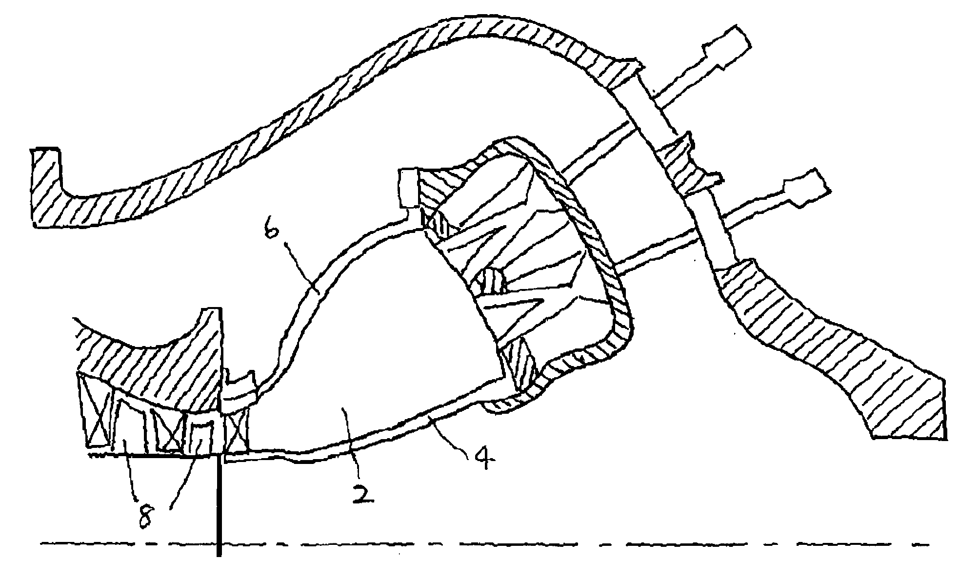
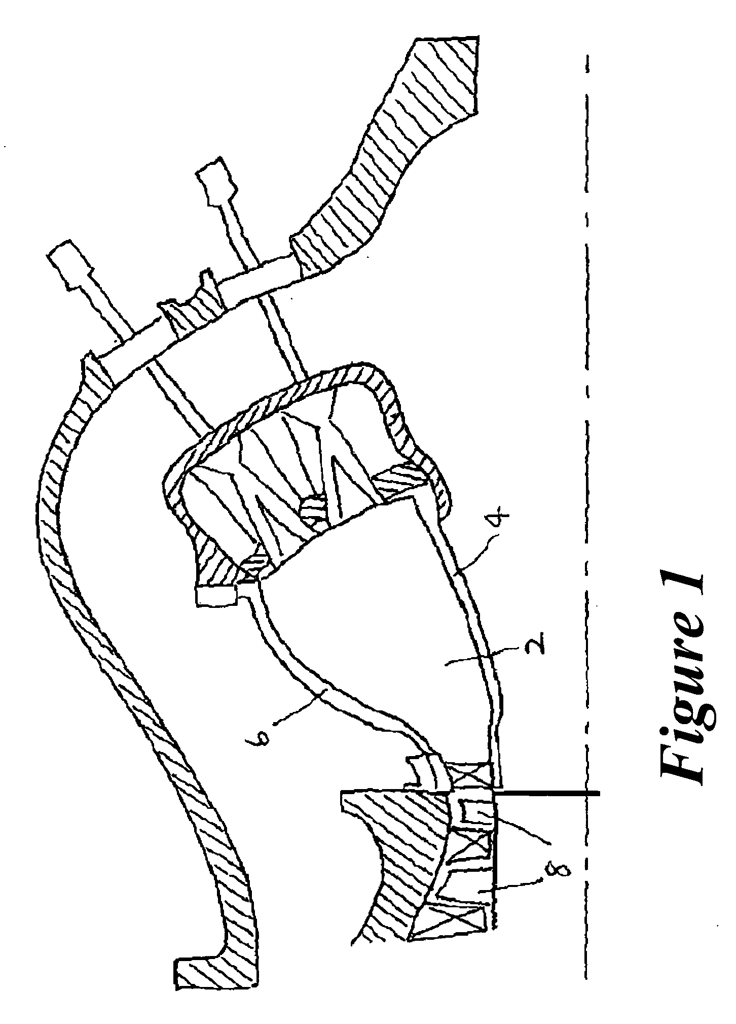
[0028]FIG. 1 shows part of a gas turbine engine in which an annular combustion chamber 2 is formed by a radially inner combustor liner 4 and a radially outer combustor liner 6. A mixture of compressed air and fuel is supplied to the combustion chamber 2 where it is ignited and the resulting gases are used drive a series of moving blades 8. Although the invention is described below with reference to the inner combustor liner 4, it will be readily appreciated that the outer combustor liner 6 can be formed in the same way.

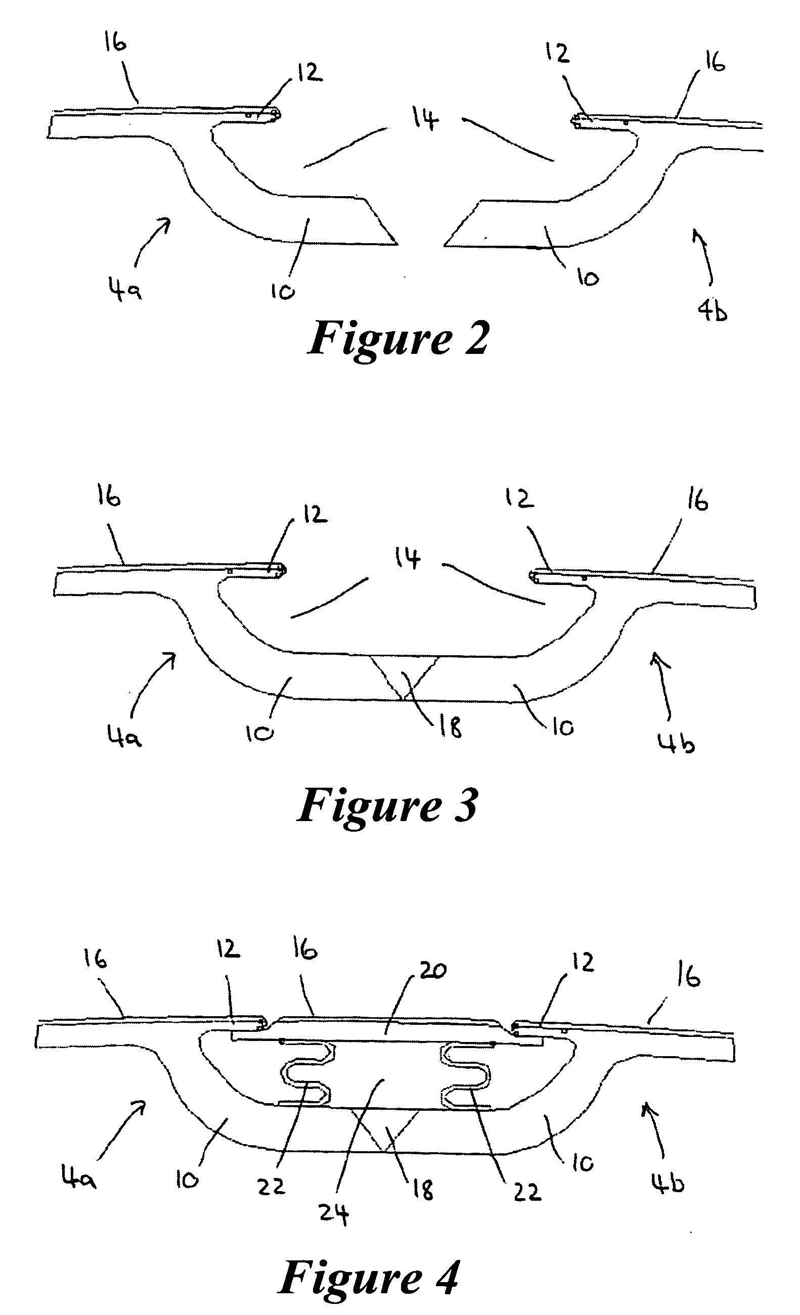
[0029] The inner combustor liner 4 is formed from two or more individual liner sections made of the commercially available alloy Inconel 617. To construct the inner combustor liner 4, the liner sections are joined together along their axially extending edges. The way in which two adjacent liner sections 4a and 4b are joined together will now be explained with reference to FIGS. 2 to 4. Each liner section 4a and 4b has a pair of axially extending edges (only one of wh...


PUM


Abstract

A combustor liner for use in a gas turbine engine includes a first liner section and a second liner section. They are joined together by welding or a mechanical fixing along a common join line or weld. A heat shield extends along the join line to protect it from the high temperatures and thermal stresses that are experienced by the combustor liner during the operation of the gas turbine engine. The heat shield is spaced apart from the joint line to define a passage between the heat shield and the first and second liner sections for the introduction of a cooling fluid such as air. The heat shield and the exposed surfaces of the liner sections are coated with a thermal barrier coating.

Description

FIELD OF THE INVENTION [0001] The present invention relates to combustor liners for use in gas turbine engines, and in particular to combustor liners that are formed from two or more liner sections that are welded or mechanically joined together. Description of the Related Art [0002] In a gas turbine engine, a mixture of compressed air and fuel is supplied to a combustion chamber where it is ignited and the resulting gases are used drive a turbine. The combustion chamber is defined by radially inner and outer combustor liners. These are often formed in a number of separate sections and are welded or mechanically joined together during the assembly of the gas turbine engine. To protect the inner and outer combustor liners from the high temperatures that are generated within the combustion chamber, it is generally preferred that the exposed inner surfaces are coated with a thermal barrier coating (TBC) such as yttria partially stabilized zirconia (YSZ), which exhibits resistance to th...

Claims


Application Information

Patent Timeline
IPC IPC(8): F23R3/42
CPCF02K9/64F23R3/002F23M2900/05003
Inventor WEBB, RENE JAMES
Owner ANSALDO ENERGIA SWITZERLAND AG
Why Eureka
Try Eureka