
Multipurpose engine controller

a multi-purpose engine and controller technology, applied in the direction of machines/engines, speed sensing governors, instruments, etc., can solve the problems of engine in which oil is sufficiently pooled in the crankcase, work machines producing severe vibrations, engine stoppage, etc., to achieve smooth lubrication, improve work efficiency of work machines in which a multi-purpose engine is mounted, and ensure the durability of the multi-purpose engin

Active Publication Date: 2007-08-09
HONDA MOTOR CO LTD
View PDF4 Cites 13 Cited by
  • Summary
  • Abstract
  • Description
  • Claims
  • Application Information

AI Technical Summary

Benefits of technology

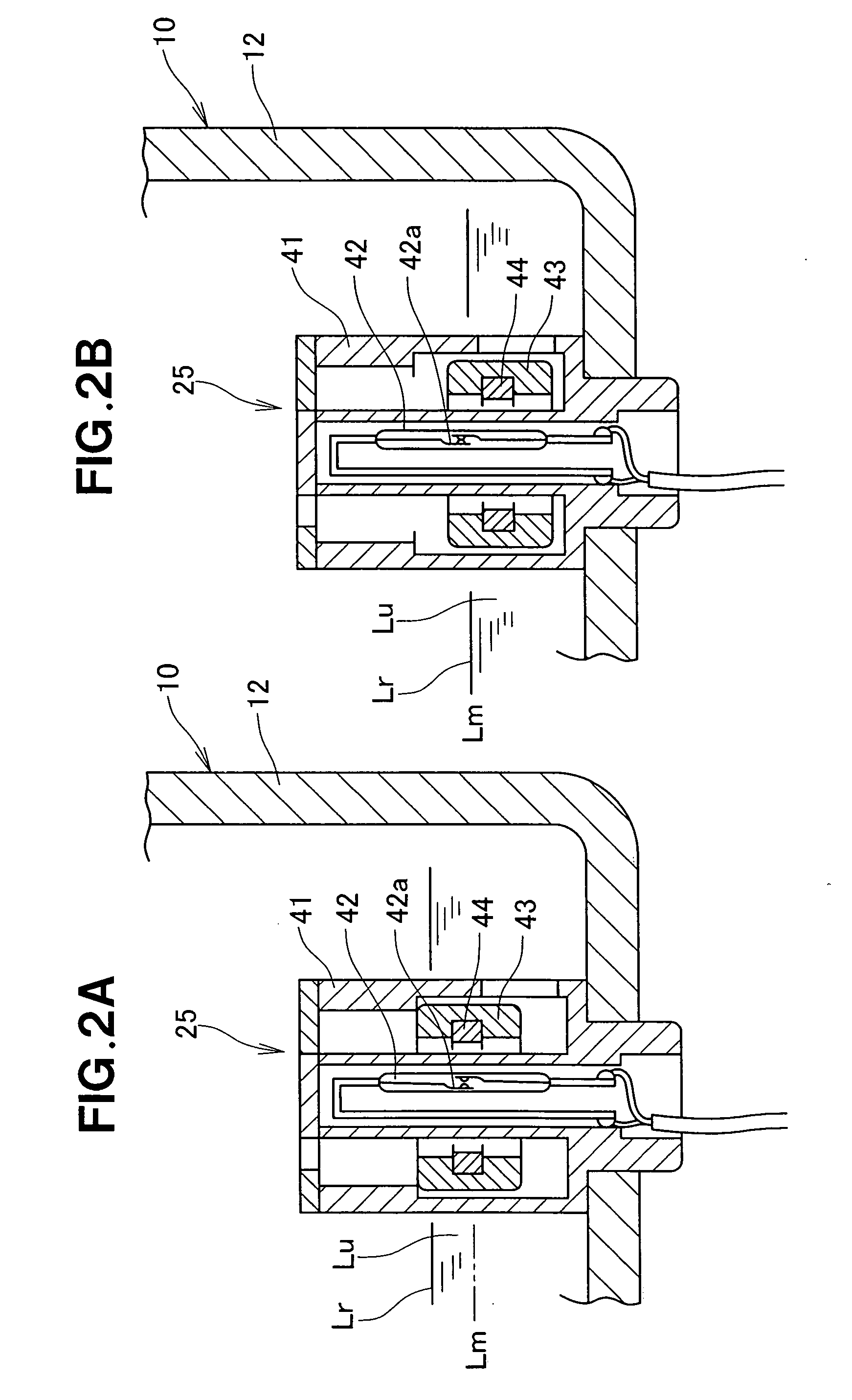
[0015]When the float-type oil level sensor has detected that the oil level has dropped at startup or during operation of the multipurpose engine, the control unit can control the ignition circuit so that the multipurpose engine is prevented from starting up. The multipurpose engine can be started only when the oil is at a suitable level. When the multipurpose engine has started, the sliding parts can be smoothly lubricated by the oil. As a result, the durability of the multipurpose engine can be assured.
[0016]On the other hand, when the oil level is adequate, the multipurpose engine is not required to be stopped, even if the surface of the oil severely and considerably fluctuates and temporarily tilts, because oil is sufficiently pooled in the crankcase after the multipurpose engine has been started. Therefore, the work efficiency of the work machine in which a multipurpose engine is mounted can be improved.
[0017]Thus, the operating state of the multipurpose engine and the state of the oil level are determined based on two detection signals, i.e., the speed signal of the multipurpose engine and the oil level drop signal, and a multipurpose engine can be easily and reliably started and stopped based on the operating state of the multipurpose engine and the state of the oil level.

Problems solved by technology

Some of the work machines produce severe vibrations, and in some work machines the orientation of the multipurpose engine can be temporarily tilted at a considerable angle.
In this case, however, an engine in which oil is sufficiently pooled in the crankcase would still stop when the surface of the oil severely and considerably fluctuates during work, or when the oil detector detects that the oil level has dropped when the engine is temporarily tilted.
As a result, work would have to be suspended.

Method used


Image

  • Multipurpose engine controller
  • Multipurpose engine controller
  • Multipurpose engine controller

Examples


Embodiment Construction

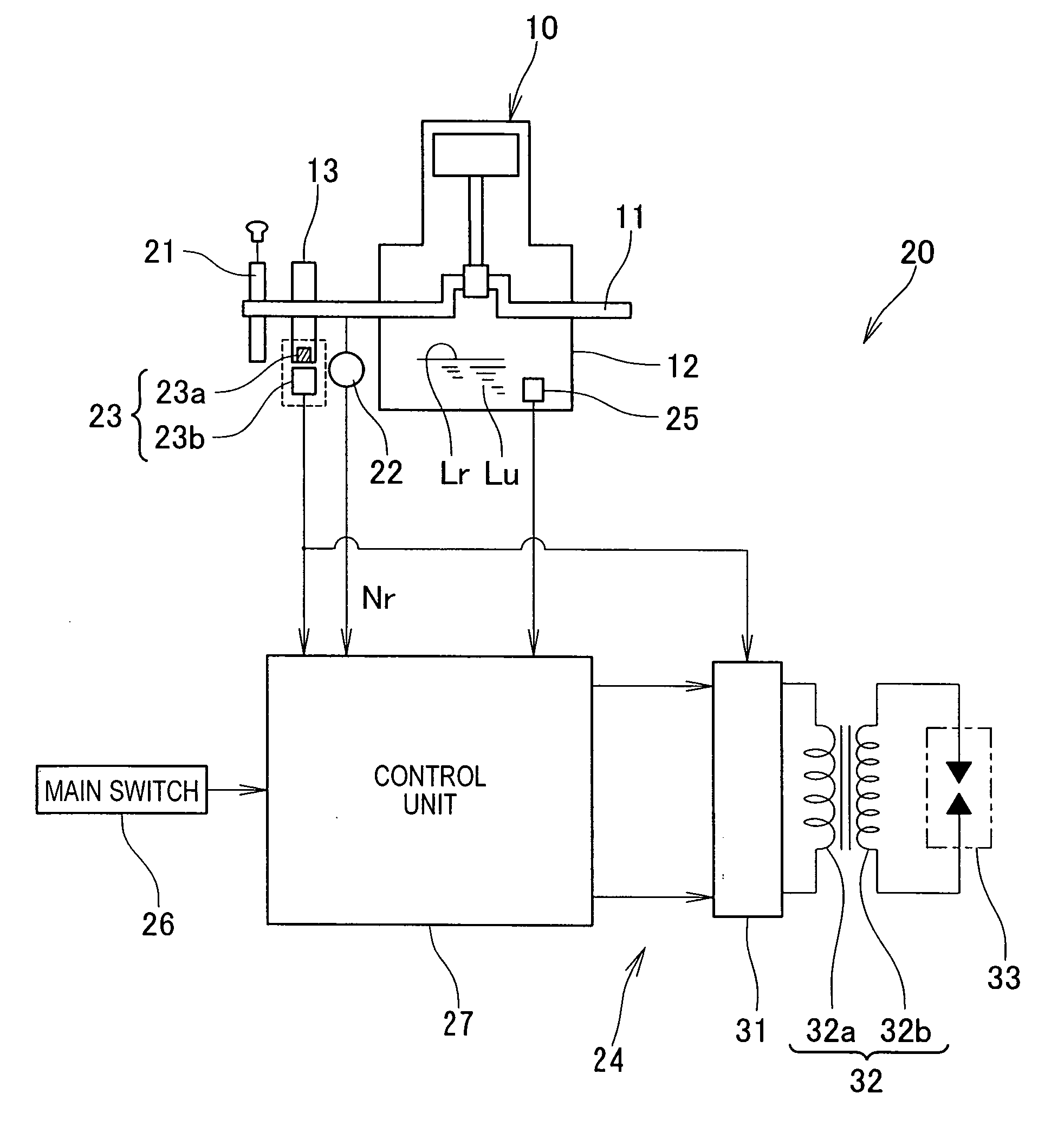
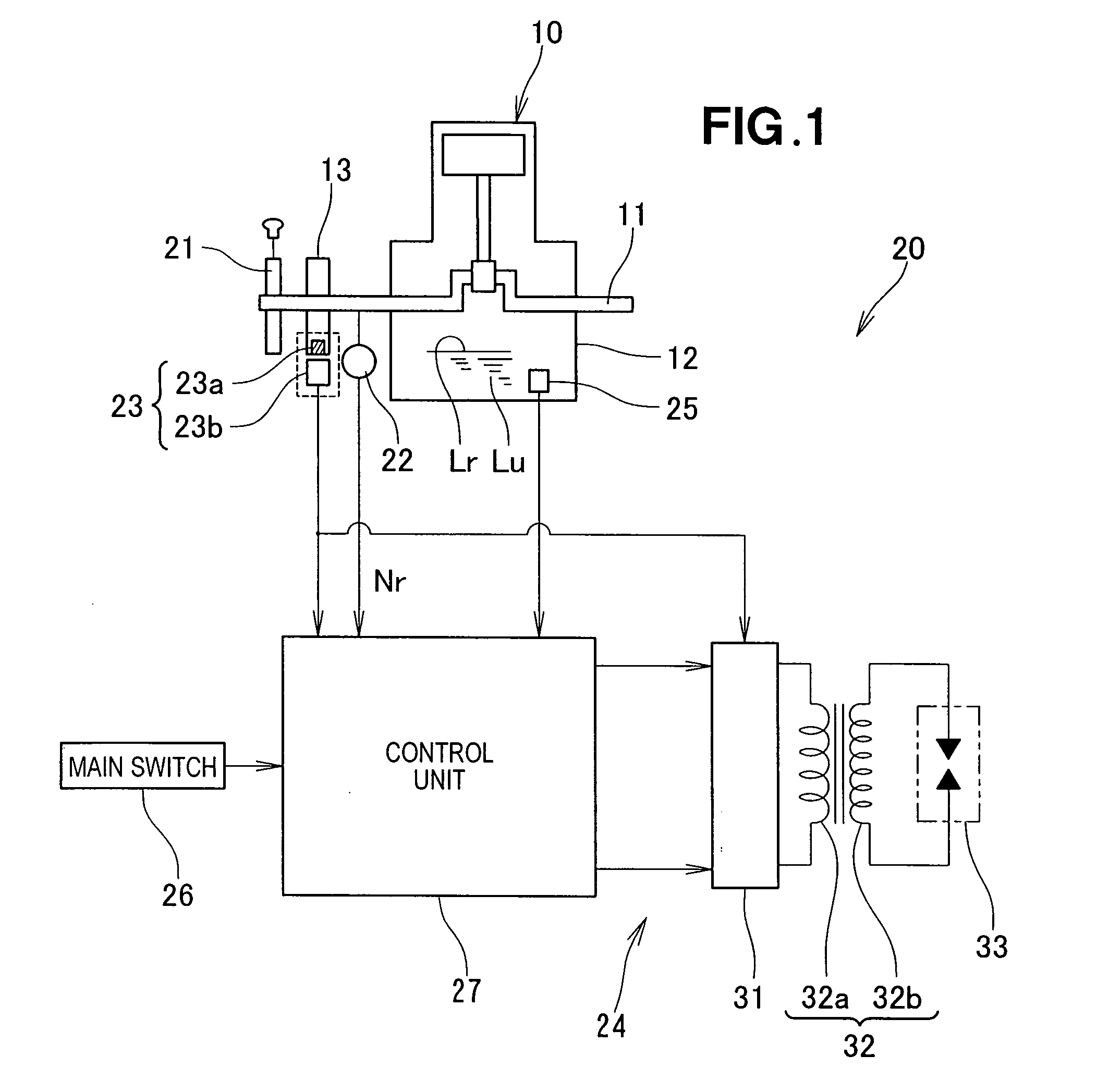
[0029]An engine 10 comprises a substantially horizontal crankshaft 11, a crankcase 12, and a recoil starter 21, and is a single-cylinder multipurpose engine mounted in work machines, as shown in FIG. 1. The engine 10 is lubricated by a method in which the sliding parts are lubricated with oil Lu pooled in the crankcase 12. The operation of the engine 10 is controlled by a multipurpose engine controller 20.

[0030]The multipurpose engine controller 20 is provided with an engine speed sensor 22, a generator 23, an ignition device 24, a float-type oil level sensor 25, a main switch 26, and a control unit 27. The multipurpose engine controller 20 is not provided with a battery.

[0031]The recoil starter 21 is a starting device that allows an operator to manually start the engine, and is provided to the crankshaft 11 or flywheel 13. The flywheel 13 is directly connected to the crankshaft 11.

[0032]The engine speed sensor 22 detects the speed (speed of revolution) of the engine 10, i.e., the s...


PUM


Abstract

A multipurpose engine controller comprises a control unit for switching between supplying and stopping power supplied from an ignition circuit to a spark plug on the basis of two states, i.e., the operating state of the multipurpose engine determined based on a detection signal from the engine speed sensor, and the state of the level of the oil inside the crankcase determined based on a detection signal from the float-type oil level sensor.

Description

FIELD OF THE INVENTION[0001]The present invention relates to a multipurpose engine controller whereby the operation of a multipurpose engine mounted in a work machine is controlled on the basis of an oil level.BACKGROUND OF THE INVENTION[0002]A method (hereinafter referred to as the “oil reservoir method”) in which sliding parts are lubricated by oil pooled in a crankcase is widely used as the lubricating method for an engine. Engines that use the oil reservoir method are mounted in work machines.[0003]In oil-reservoir engines, the pooled quantity of oil, i.e., the oil level, must be at a suitable level for the sliding parts to be smoothly lubricated. Japanese Patent Post-Exam Publication No. 53-44615 (JP-53-44615B) and Japanese Laid-Open Patent Publication No. 2004-150374 (JP-2004-150374A) disclose oil level detectors that detect the oil level.[0004]The oil level detectors disclosed in JP-53-44615B and JP-2004-150374A are mounted in vehicle engines and are provided with a float swi...

Claims


Application Information

Patent Timeline
Patent Type & Authority Applications(United States)
IPC IPC(8): F02P9/00
CPCF01M11/12
Inventor MIYASHITA, KAZUMINISHIDA, KAZUTOMONAKAMURA, TOSHIKAZUTANIGUCHI, TORU
Owner HONDA MOTOR CO LTD
Learn More