Magnetic head having notched first magnetic pole

Inactive Publication Date: 2007-08-09
WESTERN DIGITAL TECH INC
View PDF7 Cites 2 Cited by
  • Summary
  • Abstract
  • Description
  • Claims
  • Application Information

AI Technical Summary

Benefits of technology

[0007] The present invention includes a multi-step process for notching the P1 pole of the write head element of a magnetic head. In a first step following the fabrication of the P2 pole tip, a layer of protective material is deposited upon the magnetic head surfaces such that portions of the protective material layer are formed on the approximately vertical side surfaces of the P2 pole tip. Thereafter, a reactive ion etching step is performed utilizing reactive species that preferentially remove portions of the protective material. Due to the strong directionality of the RIE process, the protective material is removed from horizontal surfaces, whereas the protective material formed on the approximately vertical side surfaces of the P2 pole tip is not removed. Following the first RIE step a first ion milling step, utilizing a species such as argon, is performed to mill through the write gap layer and to notch into the P1 pole layer therebelow. The removal of redeposited material from the side surfaces of the P2 pole tip is thereafter accomplished and the protective material formed on the side surfaces of the P2 pole tip protects the P2 pole tip during the redeposition clean up step. Thereafter, a second RIE step is performed to remove the protective material from the side surfaces of the P2 pole tip. Thereafter, a second ion milling step is performed to further notch the P1 pole material. This multi-step P1 pole notching process creates a deeper notching of the P1 pole with minimal detrimental milling of the side surfaces of the P2 pole tip. As a result, the width of the P2 pole tip is more accurately controlled than before, and side writing from the P2 pole tip is reduced.
[0008] It is an advantage of the P1 pole notching process of the present invention that better P2 pole tip width control is obtained.
[0009] It is another advantage of the P1 pole notching process of the present invention that it provides better protection of the side surfaces of the P2 pole tip.
[0010] It is a further advantage of the P1 pole notching process of the present invention that it provides reduced side writing from the magnetic head.
[0011] It is an advantage of the magnetic head of the present invention that it has reduced fringing magnetic fields.
[0012] It is another advantage of the magnetic head of the present invention that the areal data storage density on hard disks can be increased.

Problems solved by technology

Such fringing fields induce unwanted side writing from the magnetic head.
A problem that initially exists in the prior art P1 notching process that utilizes an argon ion beam is that the alumina write gap layer is significantly more resistant to etching by the argon ion beam than the NiFe material of the P2 pole tip and the P1 layer.

Method used


Image

  • Magnetic head having notched first magnetic pole
  • Magnetic head having notched first magnetic pole
  • Magnetic head having notched first magnetic pole

Examples


Embodiment Construction

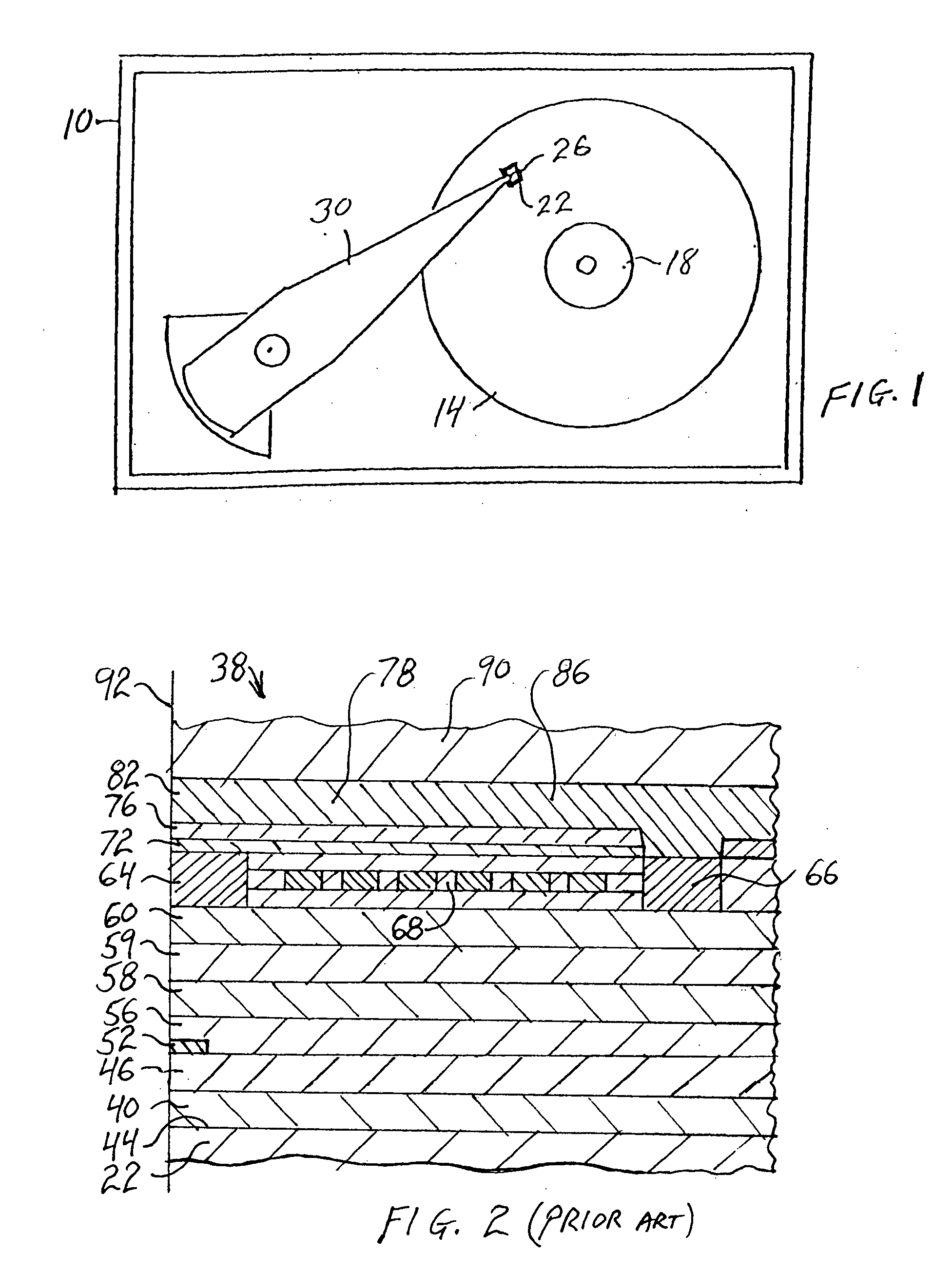
[0039] Efforts to increase areal data storage density of hard disk drives have lead to improvements in the structure and function of the write head elements of magnetic heads. A simplified top plan view of a typical hard disk drive 10 which is suitable to include the magnetic head of the present invention is presented in FIG. 1. As depicted therein, at least one hard disk 14 is rotatably mounted upon a motorized spindle 18. A slider 22, having a magnetic head 26 disposed thereon, is mounted upon an actuator arm 30 to fly above the surface of each rotating hard disk 14. A typical hard disk drive 10 may include a plurality of disks 14 that are rotatably mounted upon the spindle 18 and a plurality of actuator arms 30 having one or more magnetic heads 26 mounted upon the actuator arm. As is well known to those skilled in the art, when the hard disk drive 10 is operated, the hard disk 14 rotates upon the spindle 18 and the magnetic head 26 acts as an air bearing slider 22 that is adapted...


PUM

PropertyMeasurementUnit
Angleaaaaaaaaaa
Angleaaaaaaaaaa
Angleaaaaaaaaaa

Abstract

A multi-step process for notching the P1 pole of the write head element of a magnetic head. In a first step following the fabrication of the P2 pole tip, a layer of protective material is deposited on the approximately vertical side surfaces of the P2 pole tip. Thereafter, a first ion milling step, utilizing a species such as argon, is performed to mill through the write gap layer and to notch into the P1 pole layer therebelow. The removal of redeposited material from the side surfaces of the P2 pole tip is thereafter accomplished and the protective material formed on the side surfaces of the P2 pole tip protects the P2 pole tip during the redeposition clean up step. Thereafter, the protective material is removed from the side surfaces of the P2 pole tip, and a second ion milling step is performed to further notch the P1 pole material.

Description

BACKGROUND OF THE INVENTION [0001] 1. Field of the Invention [0002] The present invention relates generally to methods for fabricating magnetic heads, and more particularly to methods for notching the P1 magnetic pole of such magnetic heads. [0003] 2. Description of the Prior Art [0004] One approach to increasing the areal data storage density of magnetic disks is to narrow the width of the data tracks written on the disks, such that more tracks per inch can be written, and therefore more data stored on the disk in a given area. However, it is also necessary to provide some spacing between adjacent tracks, and the spacing required between data tracks is a function of the strength of the fringing magnetic fields that are created by the magnetic head. Such fringing fields induce unwanted side writing from the magnetic head. Generally, the width of the base of the P2 magnetic pole tip determines the width of the written data track. As the width of the base of the P2 pole has been reduc...

Claims


Application Information

Patent Timeline
IPC IPC(8): G11B5/147
CPCG11B5/3116G11B5/3163Y10T29/49052Y10T29/49032Y10T29/49046Y10T29/49044Y10T29/49043Y10T29/49048
Inventor BEDELL, DANIEL WAYNENIKITIN, VLADIMIRPENTEK, ARON
Owner WESTERN DIGITAL TECH INC
Why Eureka
Try Eureka