Image blur correction device and camera

a technology for image blur correction and camera, which is applied in the field of image blur correction device and camera, can solve the problems of camera shake, difficult to achieve a smaller apparatus size, and more difficult to reduce the size of the image blur correction devi

Active Publication Date: 2007-08-09
PANASONIC CORP
View PDF5 Cites 32 Cited by
  • Summary
  • Abstract
  • Description
  • Claims
  • Application Information

AI Technical Summary

Benefits of technology

[0083]Examples of a position detection element include a magnetic sensor that makes use of a hole effect (hole element).

Problems solved by technology

More specifically, with the constitutions disclosed in JPH11-258678 and JP2003-169236 it is difficult to achieve a smaller apparatus size while at the same time configuring a high-power zoom lens system.
Meanwhile, in general, when an image pickup apparatus is reduced in size, or is equipped with a high-power zoom lens system, there is a need to prevent blur of the captured image, the main cause of which is camera shake.
Accordingly, space is required for the installation of the guide shaft 103, and this makes it more difficult to reduce the size of the image blur correction device.
However, with the image blur correction device shown in FIGS. 21 and 22, there is the risk of a decrease in image blur correction performance.
This poses the risk of a decrease in the positional accuracy of the correction lens.
Thus, when size is reduced, there is the risk of a decrease in the image blur correction performance.
As a result, the manufacture becomes more complicated, and this drives up the manufacturing cost.

Method used


Image

  • Image blur correction device and camera
  • Image blur correction device and camera
  • Image blur correction device and camera

Examples


first embodiment

(1) Summary

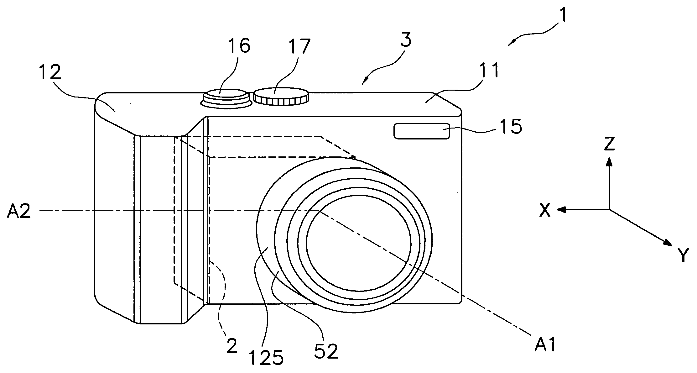
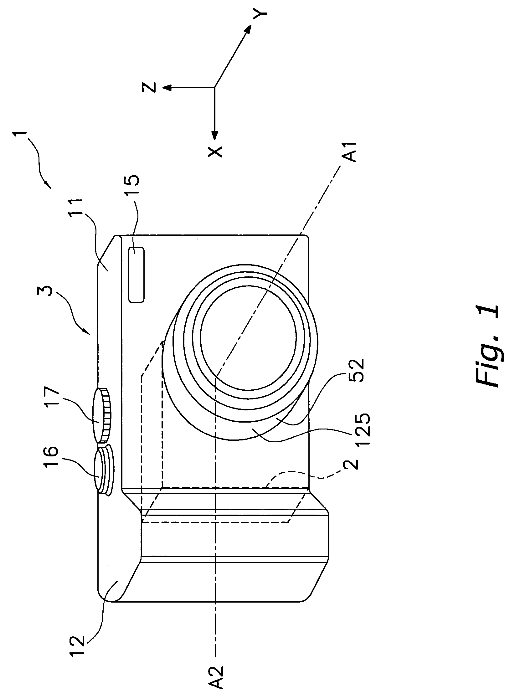
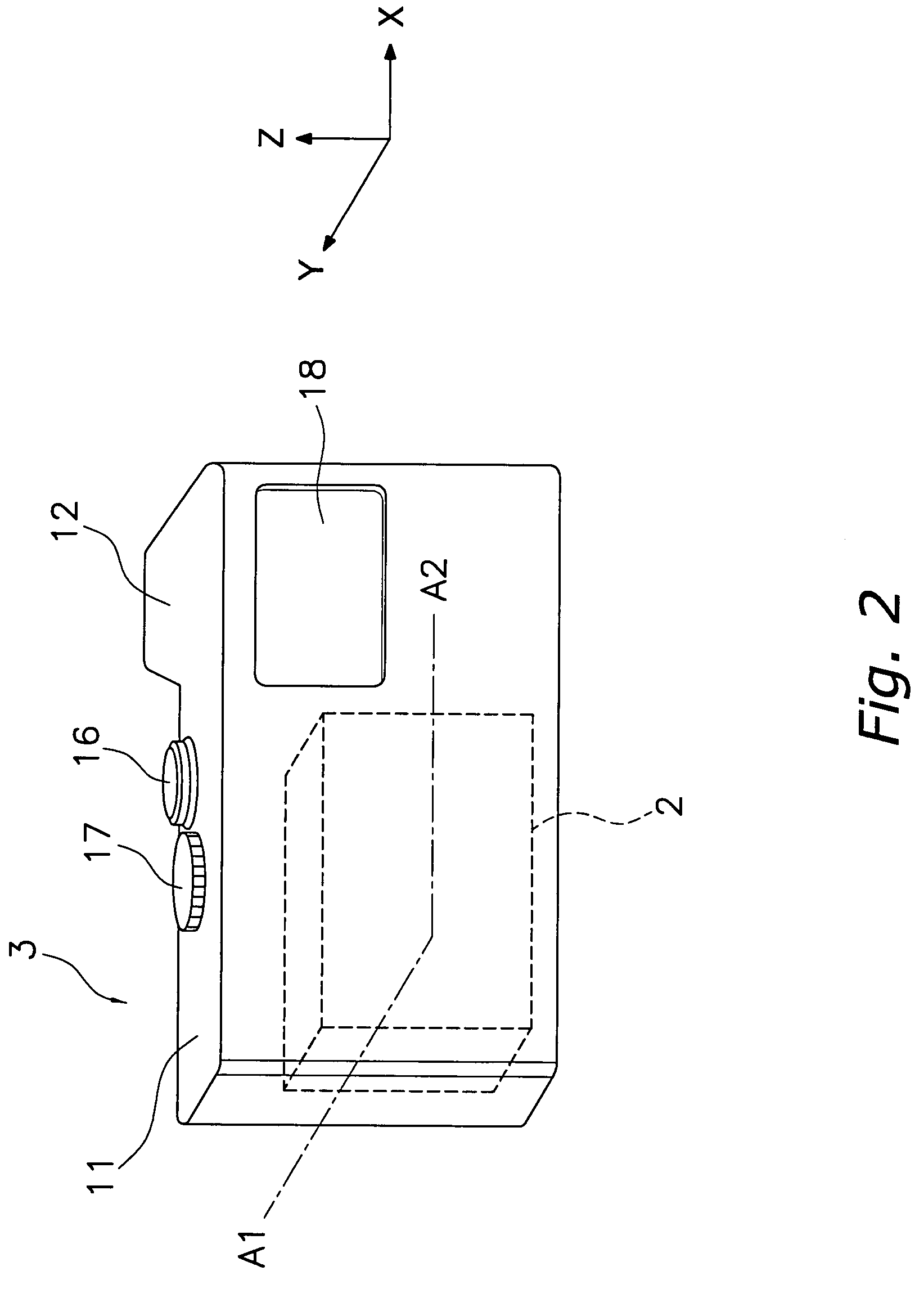
[0108]A first embodiment of the present invention will be described through reference to FIGS. 1 to 17.

[0109]The main characteristic of the digital camera of the present invention lies in the constitution of its image blur correction device. The digital camera according to this embodiment employs a folding optical system for its optical system, and the lens barrel on the subject side is formed so that it can be advanced in multiple stages. This affords a high-power zoom lens system, and also makes the apparatus more compact. A camera equipped with the image blur correction device according to the present invention is not limited to this configuration, however, and the image blur correction device according to the present invention can also be mounted in a camera that does not have a folding optical system.

(2) Digital Camera

[0110]The digital camera of the first embodiment of the present invention will be described through reference to FIGS. 1 to 3.

(2.1) Constitution of Dig...

second embodiment

[0237]With the image blur correction device 400 discussed above, the yawing movement frame 408 is movably supported by the third group frame 462, but a yawing movement frame may instead be rotatably supported by a pitching movement frame, as with the image blur correction device 500 shown in FIG. 18, for example. In this case, a pitching movement frame 505 is supported by a third group frame 562 via a pitching guide mechanism 570 so as to be capable of linear motion in the yawing direction. A yawing movement frame 508 is fixed to an electrical board 506. The yawing movement frame 508 and the electrical board 506 are rotatably supported by the pitching movement frame 505 via a yawing guide mechanism 580. The third lens group G3 is fixed to the yawing movement frame 508. The pitching movement frame 505 and the yawing movement frame 508 are rotatably linked by a pin 530. The pitching movement frame 505 is supported with respect to the third group frame 562 by three support components.

[...


PUM


Abstract

An image blur correction device 400 includes a pitching movement frame 405, a yawing movement frame 408, and a third group frame 462. The pitching movement frame 405 supports a third lens group G3 included in an optical system for performing image blur correction. The yawing movement frame 408 supports the pitching movement frame 405 to be movable in the pitching direction perpendicularly intersecting a second optical axis A2, within a plane perpendicularly intersecting the second optical axis A2. The third group frame 462 supports the yawing movement frame 408 to be movable in the yawing direction along an arc whose center is a rotational axis A3, within a plane perpendicularly intersecting the second optical axis A2.

Description

CROSS-REFERENCE TO RELATED APPLICATIONS[0001]This application claims priority to Japanese Patent Application No. JP2006-031463 filed on Feb. 8, 2006. The entire disclosures of Japanese Patent Application No. JP2006-031463 is hereby incorporated herein by reference.BACKGROUND OF THE INVENTION[0002]1. Field of the Invention[0003]The present invention relates to an image blur correction device and a camera, and more particularly relates to an image blur correction device that drives a correction lens and performs image blur correction, and to a camera equipped with this image blur correction device.[0004]2. Description of the Related Art[0005]Digital cameras that make use of image sensors such as a CCD (Charge Coupled Device) or CMOS (Complementary Metal Oxide Semiconductor) sensor to convert an optical image into an electrical signal, and record by digitizing the electrical signal, have become very popular in recent years. With these digital cameras, there is a need not only for incre...

Claims


Application Information

Patent Timeline
Patent Type & Authority Applications(United States)
IPC IPC(8): G03B17/00G03B5/00G03B17/02
CPCG03B5/02H04N5/23287H04N5/23248G02B27/646H04N23/68H04N23/687
Inventor MIYAMORI, KENICHIKONISHI, AKIOSAKAMOTO, KEIJITAKENAKA, HIDEOHASHI, HIDEYUKI
Owner PANASONIC CORP
Why Eureka
Try Eureka