Knee Brace and Methods of Use and Modification Thereof

Inactive Publication Date: 2007-08-09
BROWN ALICE M
View PDF14 Cites 8 Cited by
  • Summary
  • Abstract
  • Description
  • Claims
  • Application Information

AI Technical Summary

Benefits of technology

[0022]A knee brace constructed according to one aspect of the invention is designed to be mounted on the leg of a user to induce a side-load to correct a patello-femoral syndrome condition in a knee joint by constantly urging femur and tibia bones of the knee joint into proper alignment with one another. The side-load is applied such that it does not act on a patella of the knee joint, and thus, the petalla is able to seek its natural and proper location for tracking during flexion of the knee joint. Accordingly, the knee brace is effective in applying an oppositely directed lateral load above the knee joint, while simultaneously applying a medial load below the knee joint, or vise versa, as necessary to correct the patello-femoral syndrome condition.
[0023]According to a particular aspect of the invention, the knee brace has a main body portion with opposite sides extending between an upper portion and a lower portion. A first upper strap extends from one of the sides of the upper portion and has a free end for operable communication with the other side of the upper portion to establish one of the side loads. A first lower strap extends from the other of the sides of the lower portion opposite the first upper strap and has a free end for operable communication with the one side of the lower portion to establish the other of the side loads. As such, the knee brace effectively places the knee joint under a constant shear or side load, with one of the femur or tibia being biased laterally outwardly and the other of the femur or tibia being biased medially inwardly, relative to the unbraced condition of the knee joint. In a further aspect of the invention, the amount and intensity of the bracing, and thus, applied loads, can be readily adjusted to best accommodate the present condition of the knee joint in order to correct the patello-femoral syndrome condition to bring the knee joint into proper alignment.
[0024]Another aspect of the invention includes a method of correcting a patello-femoral syndrome in a knee joint of a leg by realigning femoral condyles of a femur in an upper leg portion above the knee joint with tibial condyles of a tibia in a lower leg portion below the knee joint through the application of a knee brace. The method includes the steps of: applying a side force in one direction on the upper leg portion with the knee brace by attaching the knee brace on an upper portion of the leg, and at the same time, applying another side force in a direction opposite the one direction on the lower leg portion by attaching the knee brace on t

Problems solved by technology

Though it may appear to the casual observer as a simple joint, in actuality, it is extremely complex.
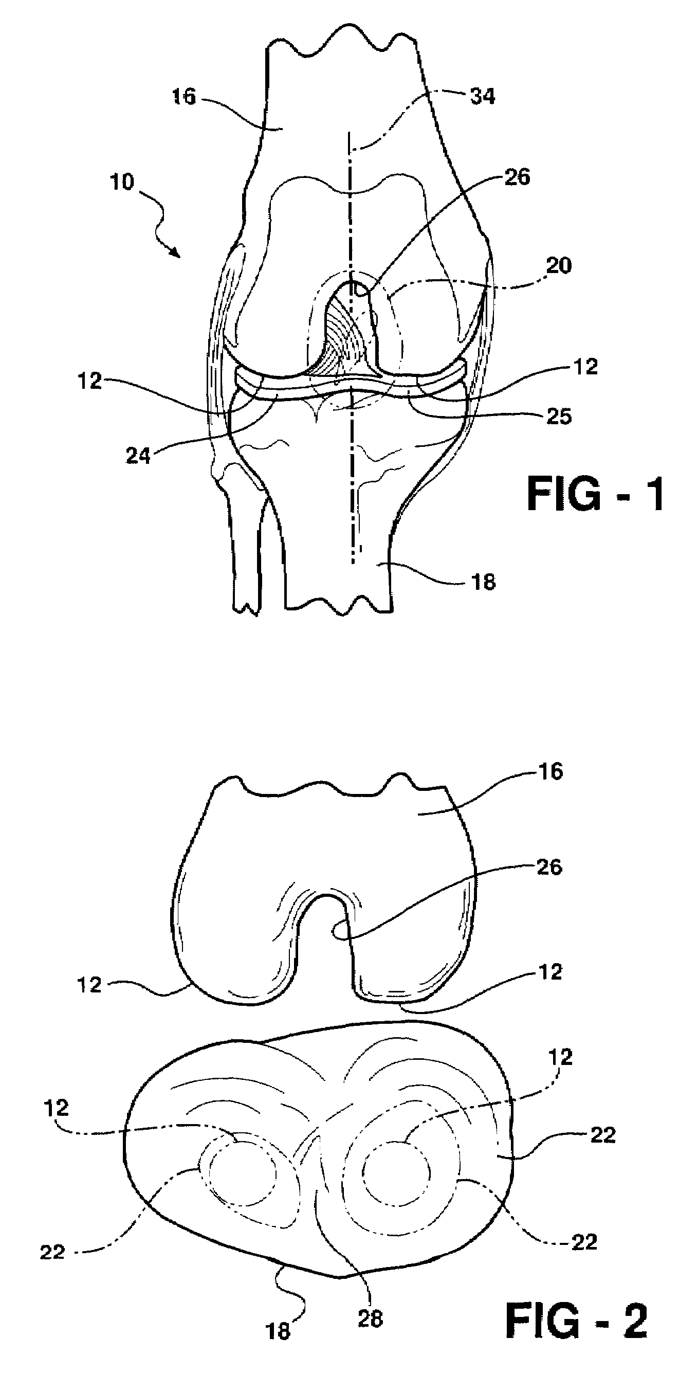
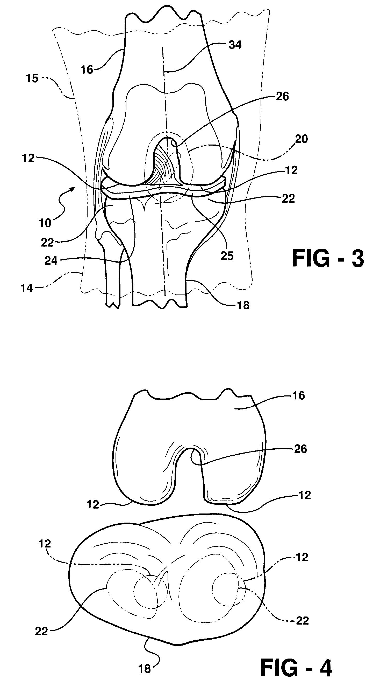
The knee joint 10 is designed to withstand generally large forces vertically, typically up to 400 pounds or more, however, it is not designed to withstand significant side forces, whether originating laterally or medially.
Unfortunately, the high degree of mobility of the knee joint 10 means it is more susceptible to being shifted off its midline plane 34 either laterally or more commonly, medially.
The shear load results in laterally opposite loads that are not desirable for normal operation of the knee joint 10.
This begins a vicious cycle in which the knee cartilage can be destroyed, and if left unchecked, the bones can be damaged.
In addition, scraping the underside of the patella 20 can result in further irritation, and thus, can eventually result in more chondromalacia being formed.
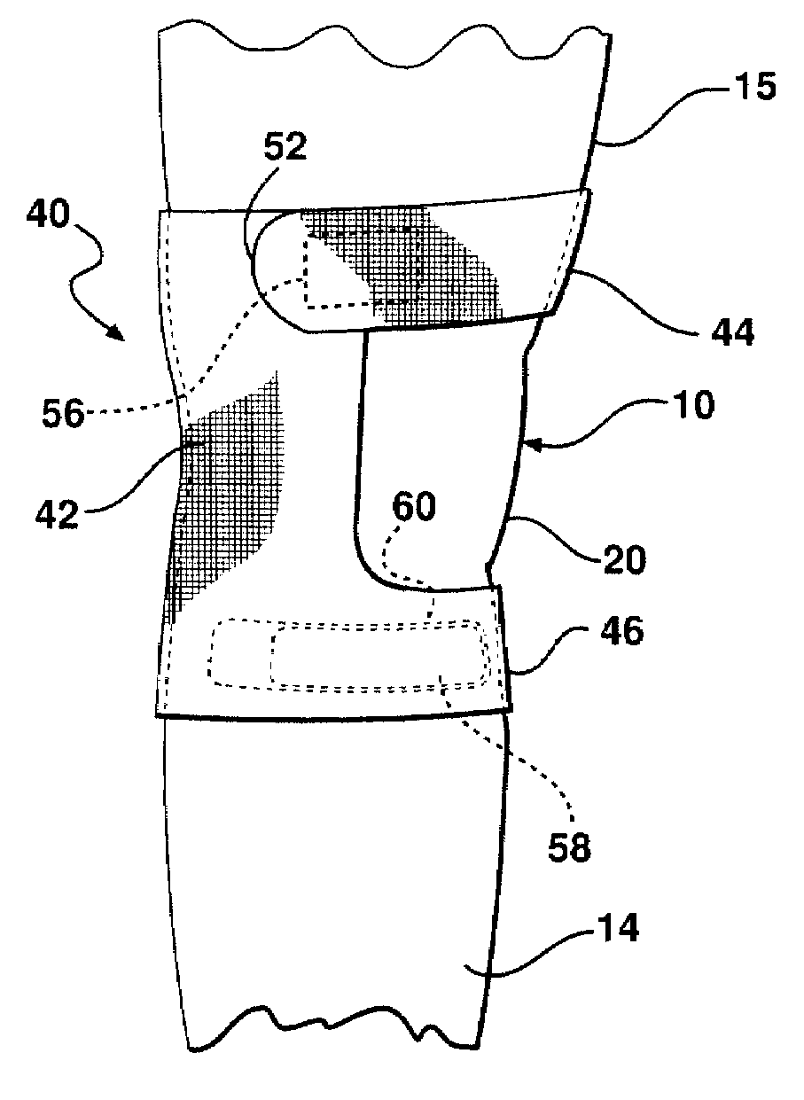
However, traditional knee braces are generally not effective in correcting the misalignment condition, or in lessening the pain associated therewith, since they typically apply equal and circumferentially uniform pressure on and around the knee joint 10 and the adjacent portions of both the lower and upper leg portions 14, 15.
Although these knee braces can be effective in restricting movement of the knee joint 10, they are largely ineffective in correcting a patello-femoral condition due to their application of equal and circumferentially uniform forces about the knee joint 10, and to their inability to

Method used


Image

  • Knee Brace and Methods of Use and Modification Thereof
  • Knee Brace and Methods of Use and Modification Thereof
  • Knee Brace and Methods of Use and Modification Thereof

Examples


Embodiment Construction

[0044]Referring in more detail to the drawings, FIGS. 8-12 show a four-way knee brace 40 constructed according to one embodiment of the invention for imparting corrective shear or side loads resulting in corresponding side pressures above and below the knee joint 10 of a user. The knee brace 40 is adjustable to apply the appropriate magnitude of side forces in the respective lateral and medial directions above and below the knee joint 10 simultaneously to correct a condition of patello-femoral syndrome. The side forces applied opposite one another above and below the knee joint 10 realign the misaligned femoral and tibial condyles 12, 22 relative to one another, and in proper alignment with the meniscus 24 (FIG. 7) therebetween. Accordingly, the knee brace 40 relieves any discomfort typically associated with the patello-femoral condition, while also preventing potential or additional damage to the knee joint 10. As such, the knee brace 40 provides a noninvasive, economical mechanism...


PUM


Abstract

A knee brace, method of use thereof, and modification to an existing knee brace facilitates inducing side loads to a knee joint to align upper and lower leg portions relative to one another, thereby allowing the knee joint to function properly over its full dynamic range of motion. The knee brace, whether as manufactured or modified, acts to apply a lateral shear force to the knee joint through application of opposing lateral forces, with one lateral force being above the knee joint in one direction and the other lateral force being below the knee joint in an opposite direction. The counteracting forces act to shift femoral condyles and tibial condyles of the knee joint back into proper lateral alignment without acting directly on the patella to counteract the effects of the patella femoral syndrome.

Description

CROSS-REFERENCE TO CO-PENDING APPLICATION[0001]This patent application claims priority to U.S. Provisional Patent Application Ser. No. 60 / 771,062, filed Feb. 7, 2006, which is hereby incorporated herein by reference in its entirety.BACKGROUND OF THE INVENTION[0002]1. Technical Field[0003]This invention relates generally to knee braces, and more particularly to knee braces worn externally about a knee joint for supporting and manipulating the knee joint.[0004]2. Related Art[0005]As is known, and shown in FIGS. 1 and 2, a knee joint 10 is the largest joint in the body and has a unique anatomy due to its unusual movement. Though it may appear to the casual observer as a simple joint, in actuality, it is extremely complex. The complexity results from the fact that the knee joint 10 has femoral condyles 12 that rotate downward and slightly medial with each flexion of a lower leg portion, then rotate slightly backward and upward with the extension of a lower leg portion 14 relative to an ...

Claims


Application Information

Patent Timeline
IPC IPC(8): A61F5/00
CPCA61F5/0106
Inventor BROWN, ALICE M.
Owner BROWN ALICE M
Why Eureka
Try Eureka