Expandable stent

a stent and expandable technology, applied in the field of expandable stents, can solve the problems of impairing the ability to hold the vessel open, permanently crushing, and peripheral arteries are particularly susceptible to external trauma, and achieve high axial flexibility in bending, long fatigue life, and high radial force. uniform

Inactive Publication Date: 2007-08-09
MED INST INC
View PDF9 Cites 36 Cited by
  • Summary
  • Abstract
  • Description
  • Claims
  • Application Information

AI Technical Summary

Benefits of technology

[0011] A stent for medical implantation is described that may overcome the limitations of current stent designs. The stent may be particularly useful in the treatment of peripheral arteries, such as the SFA. The stent is designed to provide a substantial amount of elastic (i.e., recoverable) deformation in response to an external trauma, a high and uniform radial force when deployed, high axial flexibility in bending and torsion, a long fatigue life, and a uniform circumferential stiffness.

Problems solved by technology

One challenge of designing a stent to treat the SFA is that peripheral arteries are particularly susceptible to external traumas.
Such traumas could damage an implanted stent, impairing its ability to hold the vessel open.
Conventional stents formed from, for example, 304 stainless steel tend to deform plastically (i.e., nonrecoverably) in response to applied stresses and thus may be permanently crushed by the force of such traumas.
Current stent designs do not satisfy these requirements or provide these advantages.

Method used


Image

  • Expandable stent
  • Expandable stent
  • Expandable stent

Examples


example 1

[0052] A finite element analysis (FEA) was carried out to calculate radial force for several embodiments of the present stent. These results were compared to FEA data for a prior art stent, the Cook Zilver®. In the FEA, the stents underwent a basic crimp from a 10 mm outer diameter to a 7.5 mm outer diameter while total radial force was calculated.

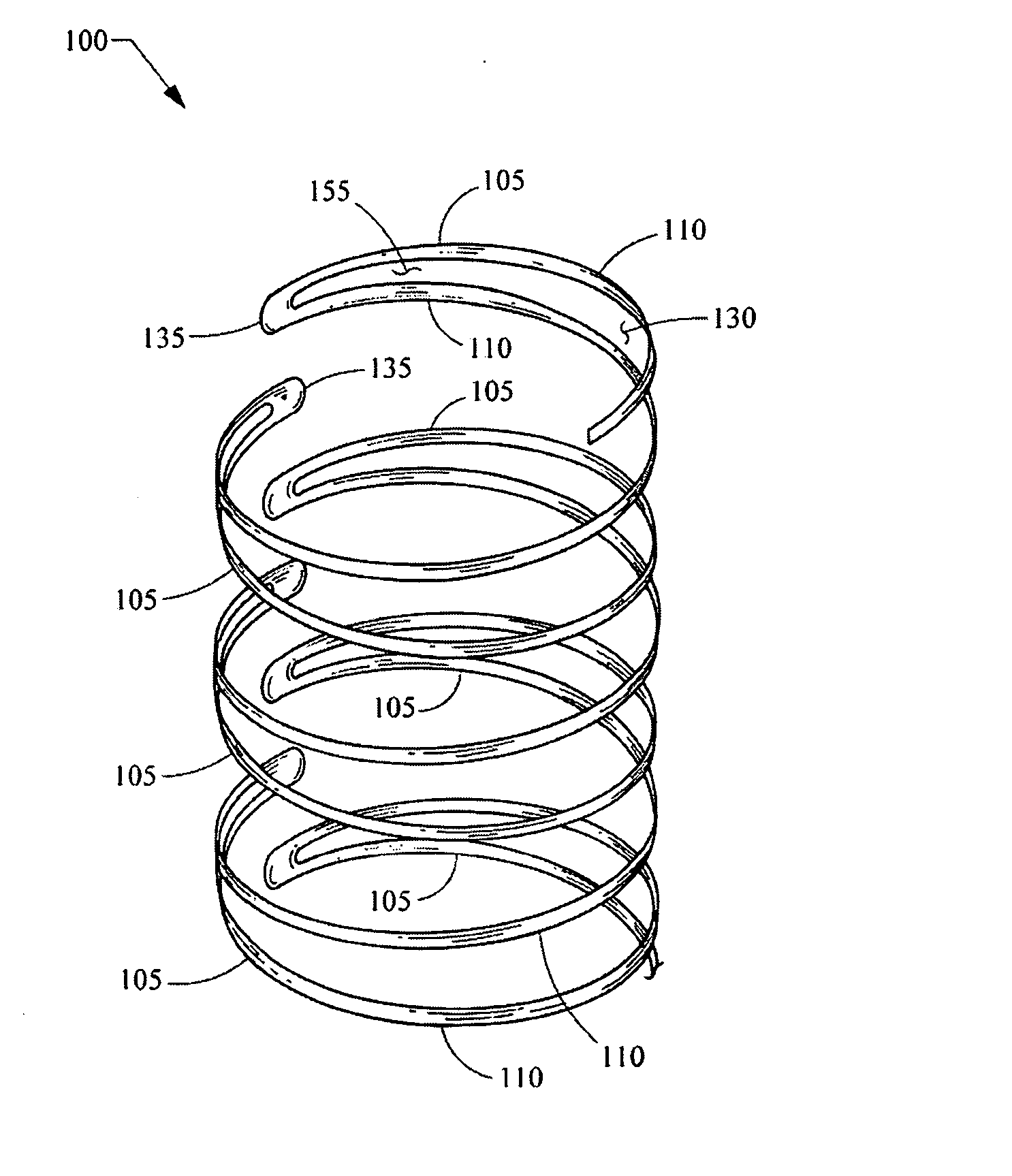
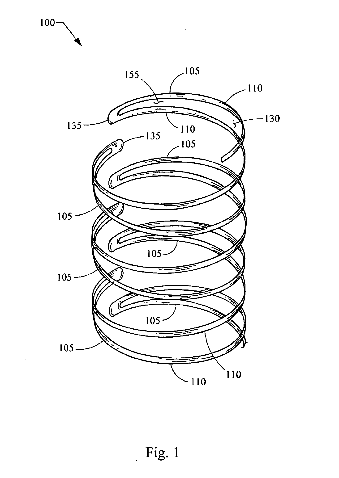
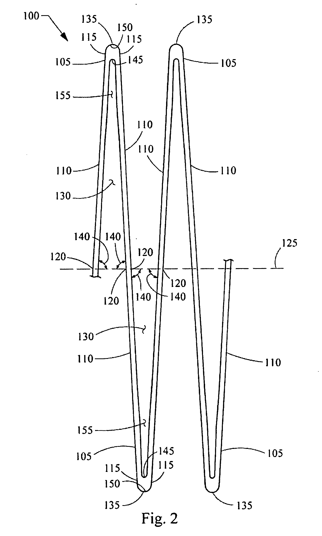
[0053] The radial force data were then normalized by the length of each stent. The results, in terms of radial force per length versus expanded diameter, are shown graphically in FIG. 10 for the following stents: a prior art stent (Zilver®, 10 mm in length); Stent 1 (10.67 mm in length), which corresponds to the first embodiment of the inventive stent as shown in FIG. 1 and FIG. 2; Stent 2 (12.84 mm in length), which corresponds to the second embodiment of the inventive stent as shown in FIG. 3 and FIG. 4; Stent 1 including a closed cell region (10.67 mm in length), which corresponds to the third embodiment of the inventive stent as shown...

example 2

[0054]FIG. 11 shows the relationship between radial force and stent thickness for the first embodiment of the inventive stent. As in the preceding example, the stents underwent a basic crimp from a 10 mm outer diameter to a 7.5 mm outer diameter while total radial force was calculated using FEA.

[0055] The FEA data presented graphically in FIG. 11 show radial force versus expanded diameter for three different stent thicknesses: 0.203 mm (0.008 inch), 0.127 mm (0.005 inch), and 0.076 mm (0.003 inch). FIG. 11 shows that radial force is highest for the largest stent thickness (0.203 mm (0.008 inch)).

[0056] The stents described herein may be advantageously used in the superficial femoral artery (SFA), which may experience large and repetitive external traumas. Such stents also may be useful in other applications. When used to treat the SFA and other peripheral arteries, the described stents may provide desirable properties to successfully treat occlusions and other conditions. For exam...


PUM


Abstract

An expandable stent for medical implantation is described which has a generally cylindrical structure with a central longitudinal axis. At least a portion of the generally cylindrical structure is formed from an arrangement of circumferentially curved structural members. The portion expands from a compressed state to an expanded state by a spiraling motion of each of the structural members about the central longitudinal axis. In the compressed state, each of the structural members may nest within an open region formed by segments composing the structural member, such that the portion of the generally cylindrical structure has no overlapping regions. A ratio of a circumferential length of each structural member to a spacing between adjacent structural members may be in the range of about 1.8 to about 2.3.

Description

EXPANDABLE STENT [0001] The present patent document claims the benefit of the filing date under 35 U.S.C. §119(e) of Provisional U.S. patent application Ser. No. 60 / 740,005, filed Nov. 28, 2005, which is hereby incorporated by reference. TECHNICAL FIELD [0002] The present invention relates generally to medical devices and more particularly to expandable stents. BACKGROUND [0003] Stents are useful in a variety of medical procedures and are often used to treat blockages, occlusions, narrowing ailments and other related problems that restrict flow through a passageway. Stents are typically designed as tubular support structures that are implanted within an artery or other vessel and then expanded from a compressed diameter to an expanded diameter. Once the stent is positioned and expanded at the area to be treated, the tubular support structure of the stent contacts and radially supports the inner wall of the passageway, thereby preventing it from closing. Stents are generally classifi...

Claims


Application Information

Patent Timeline
Patent Type & Authority Applications(United States)
IPC IPC(8): A61F2/06
CPCA61F2/885
Inventor ROEDER, BLAYNE A.SWIFT, RICHARD A.GREWE, DAVID D.
Owner MED INST INC
Why Eureka
Try Eureka