Thermal liquid flow sensor and method of forming same

Active Publication Date: 2007-08-16
HONEYWELL INT INC
View PDF24 Cites 18 Cited by
  • Summary
  • Abstract
  • Description
  • Claims
  • Application Information

AI Technical Summary

Benefits of technology

[0009] It is another aspect, to provide for a thermal liquid flow sensor which can provide flow measurements in a stable manner.
[0016] According to another aspect, a thermal liquid flow sensor has a microsensor die which has a substrate and at least one pair of temperature sensing elements disposed on the substrate. Also disposed on the substrate, preferably, between the sensing elements, is a heater for heating the liquid being measured. A hydrophilic layer is disposed on a surface region of the sensor die so as to cover the temperature sensing element and / or the heater. The liquid flow sensor advantageously exhibits enhanced sensing performance as a result of a reduction in or elimination of sensor drift normally found in existing liquid flow sensors.
[0017] By providing a hydrophilic layer on the temperature sensing elements and heater, the liquid flow sensor now has a hydrophilic surface which has a high affinity to liquid and which repels minute air bubbles away from the sensor surface. In this manner, the hydrophilic layer has a strong affinity to liquid causing minute air bubbles to be forced away from the active surface region of the sensor during sensor operation. The hydrophilic layer therefore advantageously preserves the sensor die surface and liquid interface intact and heat transfer is not obstructed by gas bubbles or film. The thermal liquid flow sensor can therefore provide liquid flow measurements in a more stable manner than existing thermal liquid flow sensors.

Problems solved by technology

However, microbridge liquid sensors intermittently exhibit drift behavior making the sensor measurements susceptible to error and instability.
Although this type of microstructure sensor is capable of reliable and rapid-response operation under harsh environments, this type of sensor still generally exhibits drift behavior which leads to measurement error.

Method used


Image

  • Thermal liquid flow sensor and method of forming same
  • Thermal liquid flow sensor and method of forming same
  • Thermal liquid flow sensor and method of forming same

Examples


Embodiment Construction

[0033] The particular values and configurations discussed in these non-limiting examples can be varied and are cited merely to illustrate at least one embodiment of the present invention and are not intended to limit the scope of the invention.

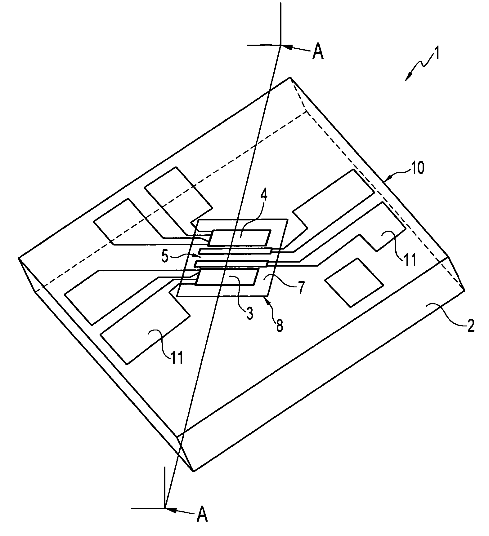
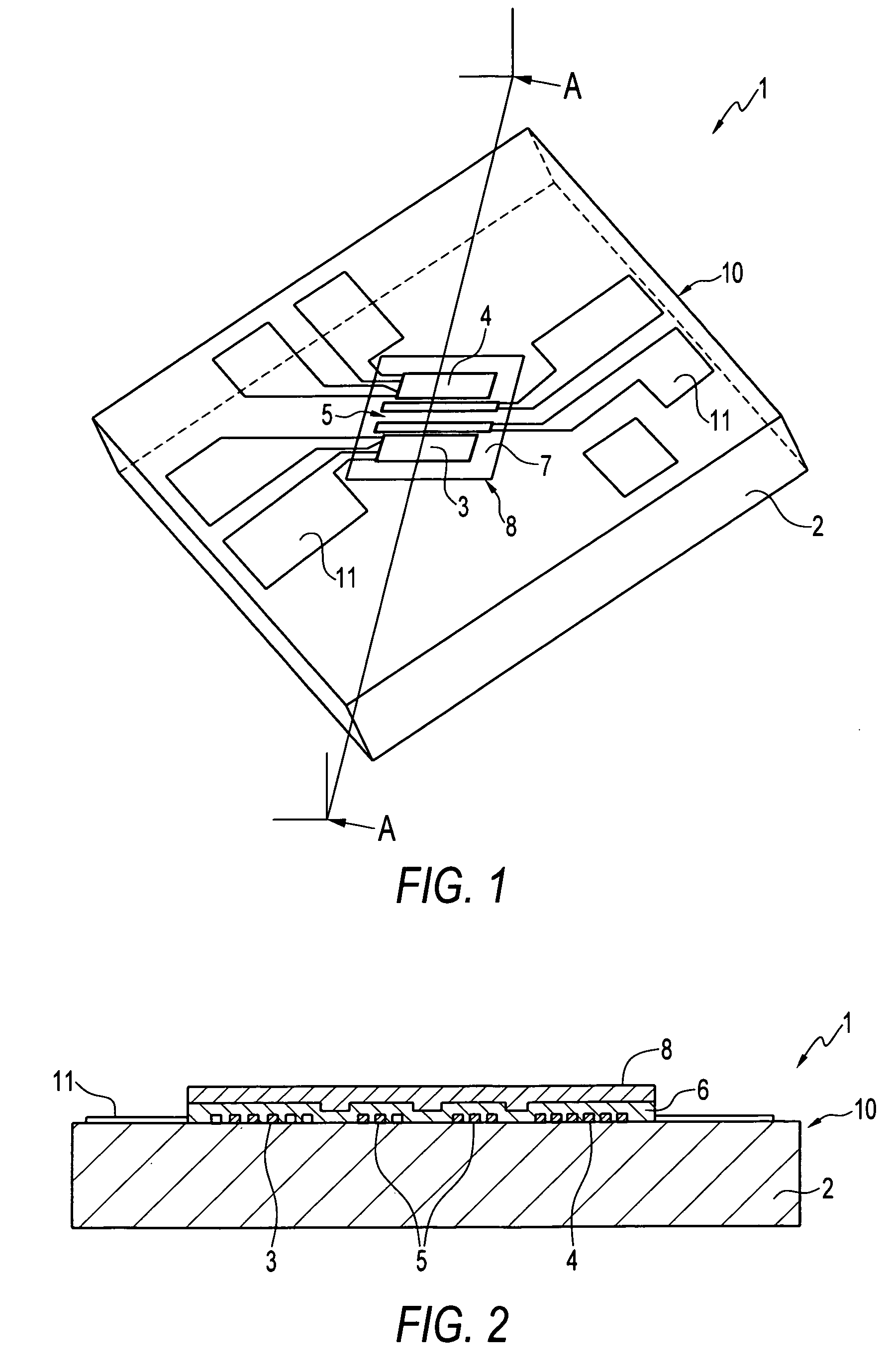
[0034] Referring the accompanying drawings, FIG. 1 illustrates a perspective view taken from above the liquid flow sensor according to one embodiment and FIG. 2 illustrates a partial cross-sectional view taken along line A-A of FIG. 1. The liquid flow sensor 1 according to one embodiment generally includes a microstructure sensor die 10 having a substrate 2, a pair of temperature sensing resistive elements 3,4 formed on the substrate 2 and a heating resistive element 5, also formed on the substrate, between the temperature sensing elements. The sensing and heating elements 3,4,5 and a surface region of the sensor die surrounding the elements define an active sensing region 7. A hydrophilic layer 8 is formed on the active sensing region 7 so a...


PUM


Abstract

A thermal liquid flow sensor and method of forming same. The sensor has a substrate and one or more sensing elements, disposed on the substrate, for sensing a property of a liquid. The liquid flow sensor, which can be for example a microsensor having a microbrick® structure, has a hydrophilic layer which is disposed on the substrate and covers the sensing element(s). The hydrophilic layer is preferably formed from a spin on glass material, such as for example a silicate or phosphosilicate. A silicon nitride layer can be disposed on the sensing element(s) and interpose the substrate and the hydrophilic layer. The silicon nitride layer can be oxidized, for example, by means of plasma oxidation or oxygen ion implantation so to form the hydrophilic layer thereon. A variety of other hydrophilic compounds can be utilized to form the hydrophilic layer such as, gold, palladium and diamond like carbon.

Description

TECHNICAL FIELD [0001] Embodiments are generally related to sensors, and in particular, to liquid flow sensors. Embodiments are also related to thermal liquid flow sensors in the form of MEMS devices and methods of manufacturing such thermal liquid flow sensors. Embodiments are additionally related to micro liquid flow sensor dies having microbrick® or microbridge configurations. BACKGROUND OF THE INVENTION [0002] Liquid flow sensors in the form of MEMS devices are configured to measure properties of liquid in contact with the sensors and provide output signals representative of the liquid flow rates. Thermal liquid flow sensors are configured to heat the liquid and measure the resulting thermal properties of the liquids to determine flow rates. Such thermal flow sensors generally include a microsensor die that includes a substrate and one or more elements disposed on the substrate for heating the liquid and sensing the liquid thermal properties. A microbridge sensor, for example as...

Claims


Application Information

Patent Timeline
IPC IPC(8): G01F1/68
CPCG01F15/006G01F1/6845
Inventor SPELDRICH, JAMIE W.BECK, SCOTT E.GEHMAN, RICHARD W.MURRAY, MARTIN G.BONNE, ULRICH
Owner HONEYWELL INT INC
Why Eureka
Try Eureka