Sewing machine

a sewing machine and needle technology, applied in the field of sewing machines, can solve the problems of increasing the production cost of sewing machines and the adverse effects of remaining needle thread, and achieve the effects of reducing the size of the cylinder bed, reducing the production cost, and ensuring reliably and accurately

Active Publication Date: 2007-08-16
BROTHER KOGYO KK
View PDF7 Cites 6 Cited by
  • Summary
  • Abstract
  • Description
  • Claims
  • Application Information

AI Technical Summary

Benefits of technology

[0013]In the above-described case, an extra amount of remaining needle thread after cutting thereof can be secured by the thread amount securing operation of the thread wiper without picker nor picker driving motor provided in the cylinder bed. Consequently, the production cost can be reduced as the result of a reduction in the number of components, and the size of the cylinder bed can be reduced. Furthermore, a necessary amount of remaining needle thread after thread cutting can be secured reliably and accurately. Additionally, since no picker is necessitated, the distance between a rotary hook and the front end of the cylinder bed can be shortened. Consequently, a sewable area can be enlarged.

Problems solved by technology

The production cost of the sewing machine is increased since the number of components is increased.
As a result, an amount of remaining needle thread tends to be adversely affected by the material of workpiece cloth or needle thread.

Method used


Image

  • Sewing machine
  • Sewing machine
  • Sewing machine

Examples


Embodiment Construction

[0025]One embodiment of the present disclosure will be described with reference to the accompanying drawings. The disclosure is applied to a multi-needle embroidery machine in the embodiment.

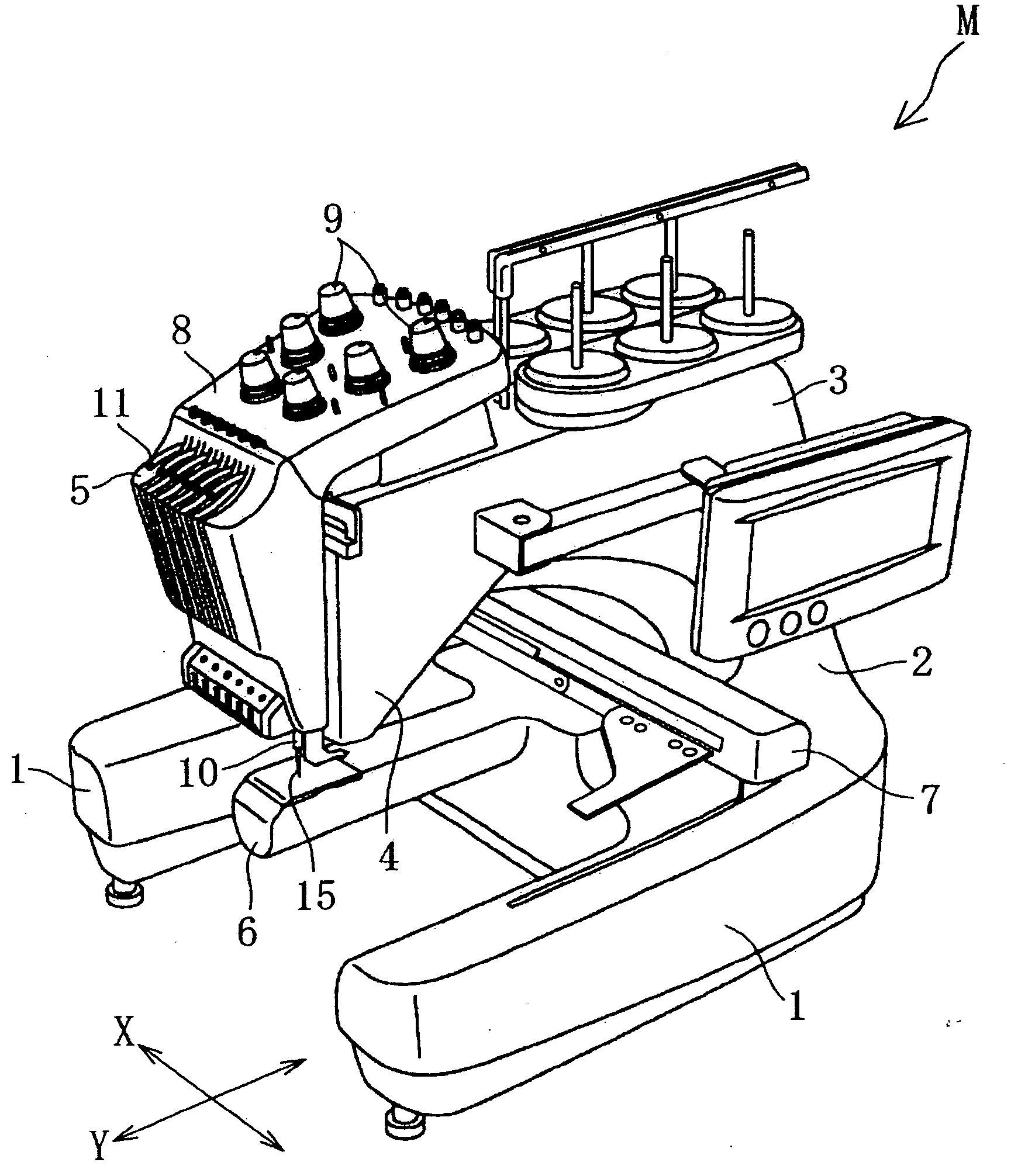
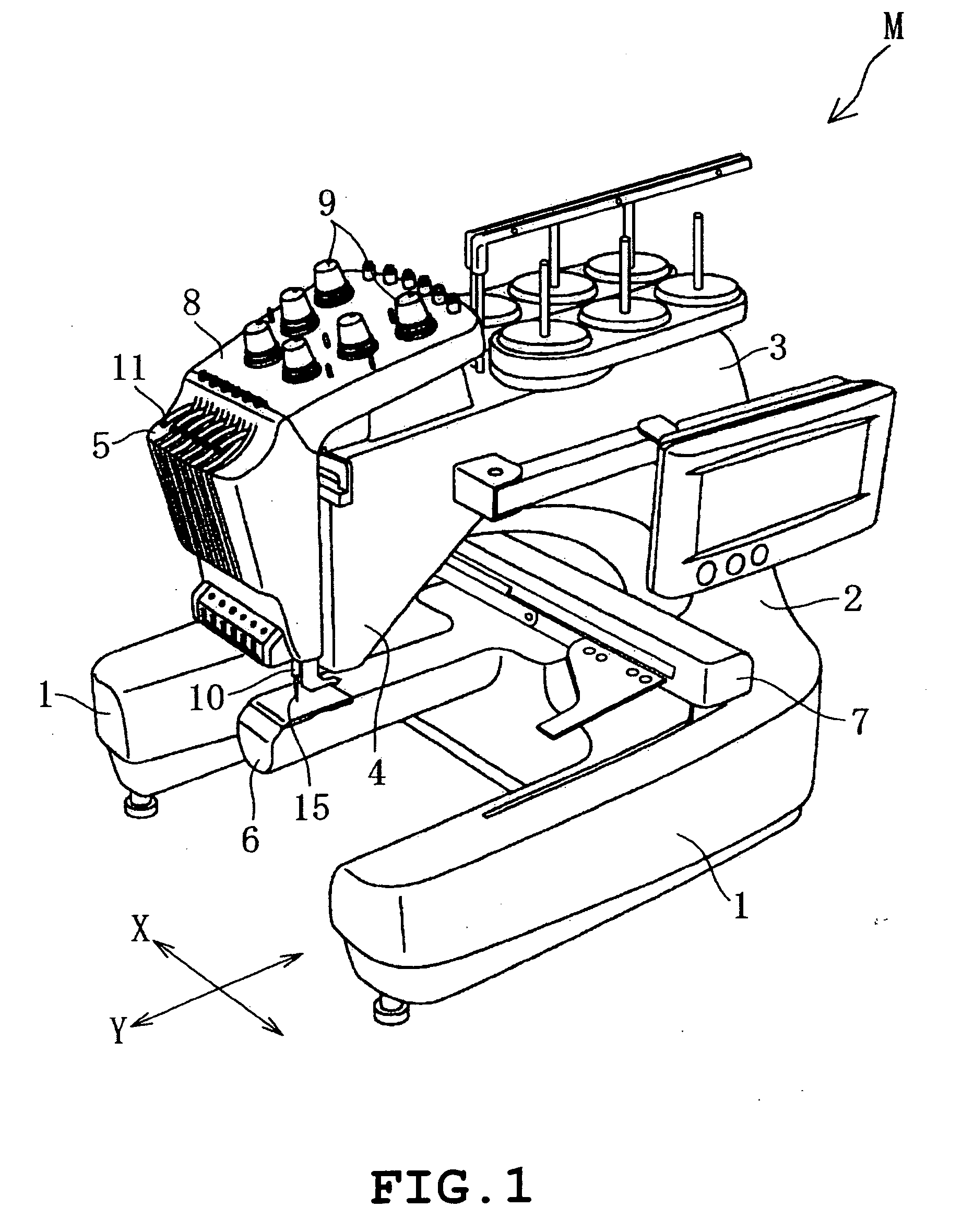
[0026]Referring to FIG. 1, the multi-needle embroidery machine M of the embodiment is shown. The multi-needle embroidery machine M includes a pair of left and right support legs 1, a pillar 2 standing from rear ends of the support legs 1, an arm 3 extending frontward from an upper end of the pillar 2, a needle bar case 5 which is mounted on a head 4 which is a distal end of the arm 3 so as to be movable horizontally, a cylinder bed 6 extending frontward from a lower end of the pillar 2, a frame moving mechanism (not shown) which moves a carriage 7 and accordingly an embroidery frame (not shown) mounted on the carriage 7 in the X-direction and the Y-direction perpendicular to the X-direction and the like. The description of the frame moving mechanism will be eliminated.

[0027]In the head 4 are pro...


PUM


Abstract

A sewing machine includes a thread take-up, a thread take-up driving mechanism driving the thread take-up, a thread cutting mechanism including a fixed cutting blade and a movable cutting blade both cutting the needle thread and a movable cutting blade driving mechanism driving the movable cutting blade, a thread wiper wiping the cut needle thread away over workpiece cloth, a wiper driving mechanism driving the thread wiper, and a control device which, upon receipt of a needle thread cutting command to actuate the thread cutting mechanism, controls the movable cutting blade driving mechanism and the wiper driving mechanism so that the thread wiper carries out a thread amount securing operation to secure a predetermined amount of needle thread located downstream relative to a needle eye of a sewing needle in a state previous to cutting of the needle thread where the needle thread is seized by the movable cutting blade.

Description

CROSS-REFERENCE TO RELATED APPLICATIONS[0001]This application is based upon and claims the benefit of priority from the prior Japanese Patent Application No. 2006-39095 filed on Feb. 16, 2006, the entire contents of which are incorporated herein by reference.BACKGROUND[0002]1. Technical Field[0003]The present disclosure relates to a sewing machine provided with a thread wiper which is actuated for securement of an amount of thread immediately before the cutting of a needle thread by a thread cutting mechanism so that a predetermined amount of needle thread located downstream relative to a needle eye of a sewing needle is secured.[0004]2. Description of the Related Art[0005]When workpiece cloth is sewn by various types of sewing machines, it has been conventionally ideal that a needle thread is prevented from dropping out of a needle eye and moreover, an end of the needle thread is prevented from remaining on an upper side of the workpiece cloth. Various types of sewing machines have...

Claims


Application Information

Patent Timeline
Patent Type & Authority Applications(United States)
IPC IPC(8): D05B65/00
CPCD05B65/06
Inventor SHIMIZU, MASAKI
Owner BROTHER KOGYO KK
Why Eureka
Try Eureka