Symmetric master cylinder lever for a hydraulic disc brake

a technology of hydraulic disc brakes and master cylinders, which is applied in the direction of cycle brakes, shock absorbers, hoisting equipment, etc., can solve the problems of increasing manufacturing costs, difficult manufacturing, and high manufacturing costs of buckley structures, so as to facilitate the construction of symmetric levers, inhibit brake performance, and eliminate air risk

Inactive Publication Date: 2007-08-16
SRAM CORPORATION
View PDF36 Cites 13 Cited by
  • Summary
  • Abstract
  • Description
  • Claims
  • Application Information

AI Technical Summary

Benefits of technology

[0006] A first aspect of the present invention is a master cylinder for a bicycle hydraulic disc brake. The master cylinder includes a cylinder wall defining a cylinder interior and a cylinder exterior. A piston is received within the cylinder interior. A port resides between the cylinder wall and a reservoir for providing fluid communication between the reservoir and the cylinder interior. A structure is provided within the reservoir for preventing any air bubbles within the hydraulic fluid from entering the port regardless of the orientation of the master cylinder. The reservoir may be defined in part by a portion of the cylinder exterior. The structure for preventing air from entering the port is preferably a protrusion extending into the reservoir, with the port being located on the protrusion. The port is preferably located on an apex of the protrusion. The reservoir may be defined in part by an elastomeric diaphragm. Extensions may be provided adjacent the port to prevent the elastomeric diaphragm from blocking the port. The portion of the cylinder exterior defining part of the reservoir is preferably a convex surface and the port is preferably located at an apex of the convex surface.
[0007] A second aspect of the present invention is a hydraulic fluid reservoir for use with a master cylinder. The master cylinder includes a cylinder in fluid communication with the reservoir. The reservoir consists of a first wall and a sidewall extending from the first wall. An elastomeric diaphragm forming a flexible wall is attached to the sidewall opposite the first wall, with the first wall, the sidewall and the flexible wall cooperating to define an interior of the reservoir. A port provides fluid communication between the reservoir interior and the cylinder. The port has a reservoir opening in the reservoir interior located in one of the first wall and the sidewall, with the one of the first wall and the sidewall being configured to extend into the reservoir interior, thereby locating the reservoir opening at a position in the reservoir interior preventing an air bubble within the hydraulic fluid in the reservoir from entering the reservoir port, regardless of the orientation of the reservoir.
[0009] The master cylinder lever of the present invention provides a unique “backpack” reservoir which prevents air from entering the cylinder of the master cylinder regardless of the orientation of the master cylinder. Thus, it eliminates the risk of air entering the cylinder and inhibiting brake performance in the event of storing the bicycle in an unintended orientation or an accidental tipping or tumble of the bicycle. In addition, the backpack reservoir facilitates construction of a symmetric lever which may be disposed on either the right or left handlebar of a bicycle without concern for enabling air to enter the cylinder. This has the further advantages of simplifying manufacturing and limiting the stocking requirements of both bicycle manufacturers and wholesale and retail distributors of master cylinder levers.

Problems solved by technology

Right and left specific master cylinder levers requires manufacturers to have two sets of tooling, which increases manufacturing costs and the complexity of the manufacturing process.
An additional problem with most prior art master cylinder levers is the reservoir for hydraulic fluid can allow bubbles within the reservoir to enter the timing or compensation ports if the master cylinder and associated reservoir attain some undesired orientation.
This structure substantially prevents air from entering the timing port or the compensating port regardless of the orientation of the master cylinder assembly, however, the structure shown in Buckley is expensive and difficult to manufacture.

Method used


Image

  • Symmetric master cylinder lever for a hydraulic disc brake
  • Symmetric master cylinder lever for a hydraulic disc brake
  • Symmetric master cylinder lever for a hydraulic disc brake

Examples


first embodiment

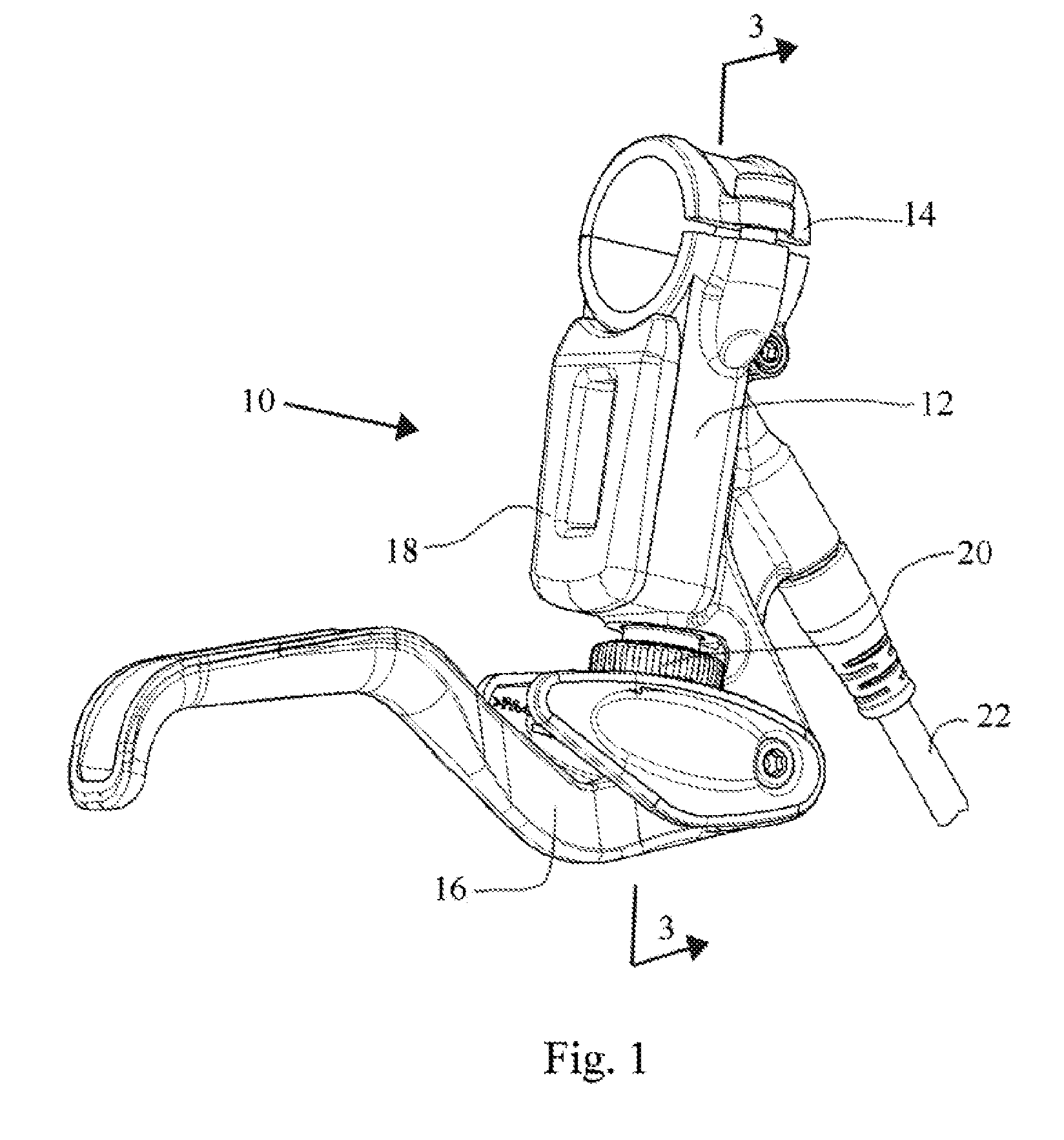
[0036] master cylinder lever assembly 10 is illustrated in a perspective view in FIG. 1. The master cylinder lever assembly consists generally of a cylinder housing 12 having a bar clamp 14 at one end and a lever handle 16 pivotably attached at an opposite end. Also seen in FIG. 1 is a reservoir cover 18 which covers a “backpack” reservoir which will be described in greater detail below. Also visible in FIG. 1 is a contact point adjustment knob 20 which is also described in greater detail below. The master cylinder housing 12 is hydraulically connected to a slave cylinder which operates a hydraulic caliper (not shown) by hydraulic line 22.

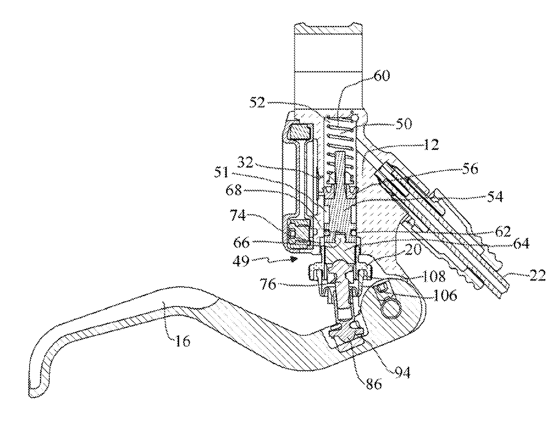
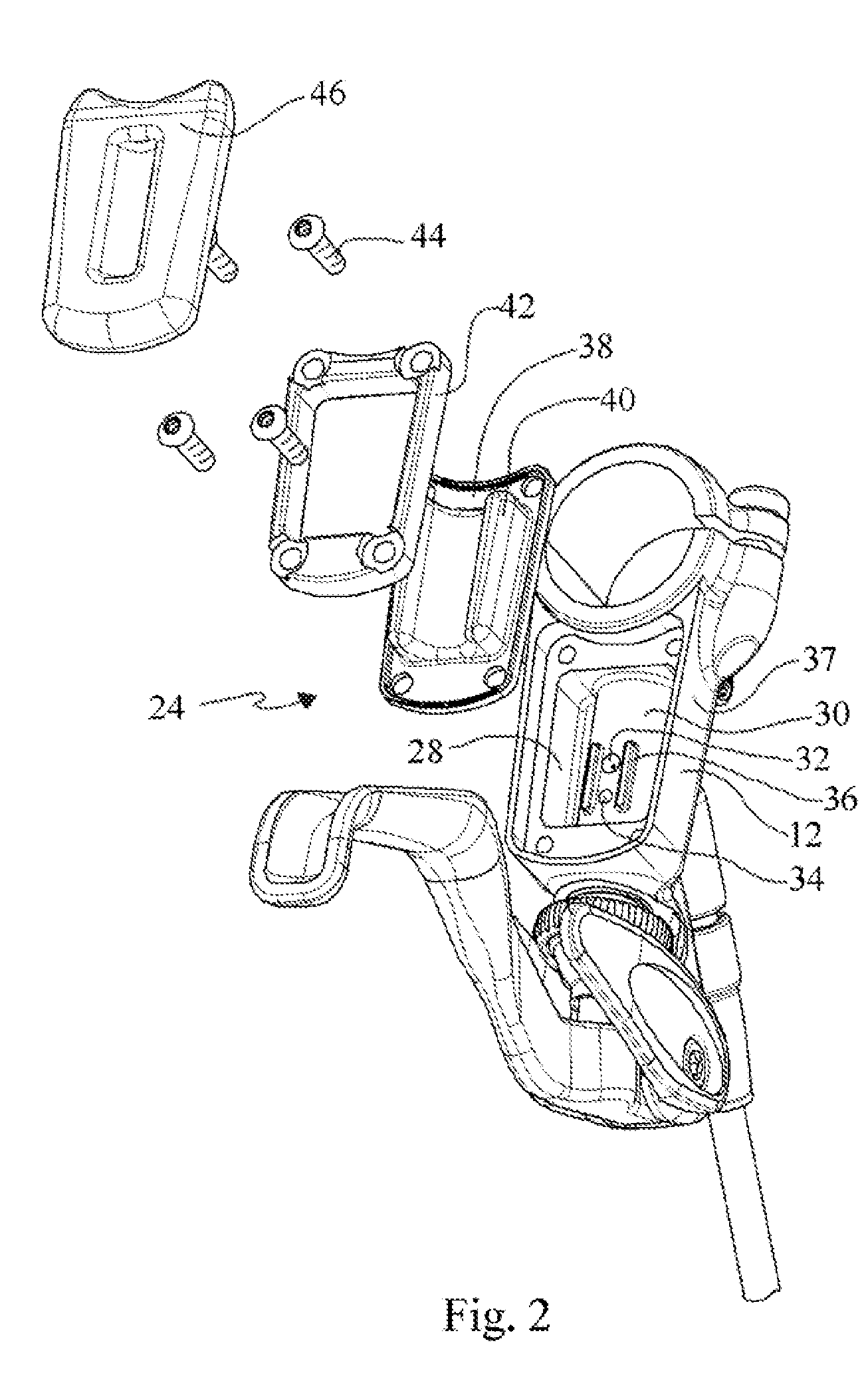
[0037]FIG. 2 is an exploded view of the “backpack” reservoir 24 of the master cylinder lever of FIG. 1. The backpack reservoir consists of a reservoir chamber 28 defined in a rear facing portion of the master cylinder housing 12. A cylinder wall 30 defining in part the cylinder of the master cylinder housing 12 extends into the reservoir chamber 28...

second embodiment

[0055] the hydraulic cylinder lever of FIG. 12 also includes a structure for compensating for movement of the push rod during dead-band adjustment to maintain the lever 206 in a select rest position. The threads between the threaded portion 236 of the push rod and the threaded bore 268 of the cross dowel 266 are configured to counteract pivoting of the handle that would otherwise occur about the lever pivot assembly 110 when the push rod 234 is moved by movement of the threaded insert 244. In other words, as the threaded insert 244 is advanced toward the second end of the cylinder, which necessarily causes the advancement of the push rod 234 toward the second end of the cylinder and which would normally cause the lever handle 206 to pivot upward, the threaded engagement between the second end of the push rod and the cross dowel tends to move the lever handle 206 downward in an amount that corresponds to what would be the upward movement so as to maintain the lever handle 206 at a se...


PUM


Abstract

A hydraulic disc brake master cylinder having a bar clamp attached to a master cylinder housing allowing the attachment of the master cylinder to a handle bar along a longitudinal clamp axis. The master cylinder also includes a cylinder wall associated with the master cylinder housing extending axially along the cylinder axis. The cylinder axis is not parallel to the longitudinal clamp axis. This embodiment further includes a reservoir for hydraulic fluid which includes a first wall which first wall includes only a radial portion of the cylinder exterior. The reservoir also includes an elastomeric diaphragm. The cylinder axis and the longitudinal clamp axis lie in a plane substantially bisecting the first wall. Thus, the symmetric master cylinder lever may be disposed on either the right or left portion of a handle bar without effecting operation of the master cylinder lever by a user.

Description

RELATED APPLICATIONS [0001] This application is a continuation of U.S. patent application Ser. No. 11 / 552,458, filed Oct. 24, 2006, entitled “Master Cylinder Lever with Independently Variable Rest Position and Engagement Point”, which is a continuation of U.S. patent application Ser. No. 10 / 966,737, filed Oct. 15, 2004, entitled “Master Cylinder Lever for a Hydraulic Disc Brake Having a Backpack Reservoir,” now U.S. Pat. No. 7,178,646, which is a continuation of U.S. application Ser. No. 10 / 316,452, filed Dec. 10, 2002, entitled “Master Cylinder Lever for a Hydraulic Disk Brake Having a Backpack Reservoir,” now abandoned, which application claims priority from U.S. Provisional Patent Application Ser. Nos. 60 / 344,450, filed Dec. 28, 2001; 60 / 416,130, filed Oct. 4, 2002; and 60 / 416,698, filed Oct. 7, 2002, each entitled “Master Cylinder Lever for Hydraulic Disc Brake.”TECHNICAL FIELD [0002] The present invention is directed toward an improved master cylinder lever for a hydraulic disc...

Claims


Application Information

Patent Timeline
Patent Type & Authority Applications(United States)
IPC IPC(8): B66D5/26B60T11/22B62L3/02
CPCB60T7/102B66D5/26B62L3/023B60T11/22
Inventor LUMPKIN, WAYNE R.
Owner SRAM CORPORATION
Why Eureka
Try Eureka